
Car repair AvtoVAZ Car repair Renault Car repair Hyundai Car repair Ford Car repair Volkswagen Car repair Audi Car repair Chevrolet
English Русский
Български
Беларускі
Український
Српски
Hrvatski
Română
Polski
Slovenský
Magyar
articles sitemap contacts bookmark
LadaMan.ru


Kalina Granta Priora Vesta Largus XRAY
Priora 1 (2007-2018, VAZ-2170)

Checking and replacing the voltage regulator with brush holder (Priora 2170)

  • Main
  • Priora
  • Priora 1
  • Electrical equipment
  • Power devices
  • Checking and replacing the voltage regulator with brush holder
0
The generator 5102.3771 is equipped with a voltage regulator mod. 5102.3771.060.

The operation of the voltage regulator consists of continuously automatically changing the excitation current of the generator in such a way that the generator voltage is maintained within specified limits when the rotation speed and load current of the generator change.

You will need: flat-blade screwdrivers, an 8 mm wrench, and a tester.
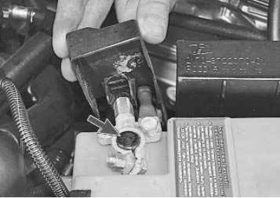
1. Remove the rubber boot and connect the positive wire of the voltmeter to the positive terminal…


1. Remove the rubber boot and connect the positive wire of the voltmeter to the positive terminal of the battery, and connect the negative wire to the negative terminal.

2. Start the engine and turn on the car headlights.

3. After 15 minutes of engine operation at medium speed measure the voltage, it should be within 13.8-14.4 V. If undercharging is observed (voltage is not within specified limits)...
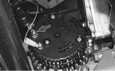
4. ...check the voltage directly at the generator power terminal (stud) relative to its housing…


4. ...check the voltage directly at the generator power terminal (stud) relative to its housing ("ground"). If the voltage at the generator stud is normal, check the voltage at the power terminal. If the tester shows different voltage values, clean the contact of the power terminal and tighten the nut securely, then repeat the measurements. After preventive measures, the difference in voltage values between the pin and the terminal should decrease to zero. If the tester readings are the same, i.e. normal, then in the same manner as described above, check the voltage on fuses F4 and F6, their contact blocks and at the point where the harness "plus" of the battery is attached to the common "plus" bus of the main fuse block. If the voltage at the alternator stud is not within specification, check the alternator drive belt tension and adjust the tension if necessary (see "Checking the alternator drive belt tension"). If the voltage is still not within the normal range, replace the voltage regulator.


5. Disconnect the wire from the negative terminal of the battery.
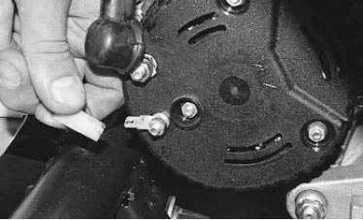
6. Disconnect the connector with the wire from the «D+» terminal of the generator.


6. Disconnect the connector with the wire from the "D+" terminal of the generator.
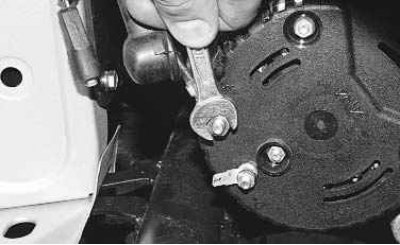
7. Remove the rubber boot, unscrew the nut...
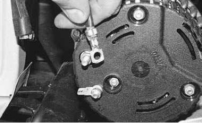

7. Remove the rubber boot, unscrew the nut...

8. ...and disconnect the wires from the contact pin.


8. ...and disconnect the wires from the contact pin.

Note: The work on replacing the voltage regulator is performed on the generator installed on the vehicle. For clarity, the generator has been removed from the vehicle.
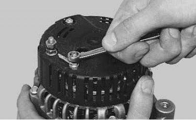


9. Loosen the nut securing the generator excitation circuit terminal...
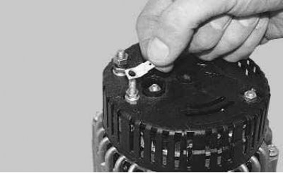

9. Loosen the nut securing the generator excitation circuit terminal...

10. ...and remove the terminal.
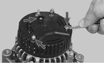

10. ...and remove the terminal.

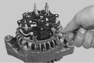
11. Unscrew the three nuts securing the plastic generator casing...
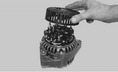

11. Unscrew the three nuts securing the plastic generator casing...

12. ...and remove the casing.

12. ...and remove the casing.


13. Unscrew the two nuts securing the voltage regulator housing...

13. Unscrew the two nuts securing the voltage regulator housing...

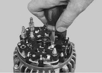
14. ... screw for fastening the regulator terminal to the «D+» bus of the rectifier unit...


14. ... screw for fastening the regulator terminal to the "D+" bus of the rectifier unit...
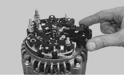
15. ...and remove the voltage regulator from the generator.
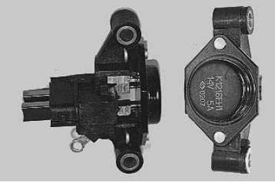

15. ...and remove the voltage regulator from the generator.

Note: This is what the voltage regulator assembly with the brush holder looks like when removed…


Note: This is what the voltage regulator assembly with the brush holder looks like when removed from the car.
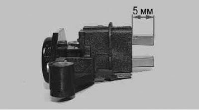


16. Check the ease of movement of the brushes in the brush holder and their protrusion. If the…


16. Check the ease of movement of the brushes in the brush holder and their protrusion. If the brushes protrude from the brush holder by less than 5 mm, replace the voltage regulator with the brush holder.

17. Install the voltage regulator in the reverse order of removal.


This article is available at russian, bulgarian, belarusian, ukrainian, serbian, croatian, romanian, polish, slovak, hungarian
This article has been reviewed: Vladislav Voloshin
Share with friends:
◀ Previous
Lada Priora 1: Power devices
Next ▶

Removal and installation the generator
Possible generator faults
Design Features of the Generator
Charging the battery
Removal and installation the battery
Generator repair
Features of the starter design
Possible starter malfunctions
Removal and installation the starter
Starter repair
More articles with information from manuals for Lada:

• Checking and replacing the voltage regulator with capacitor and brush… Lada Kalina Sedan (2004-2013, VAZ-1118)
• High Voltage Wires — Checking and Replacing Lada Granta 1 (2011-2023, VAZ-2190)
• Ignition Coil — Checking and Replacing Lada Vesta 1 (2015-2023, VAZ-2180)
• Checking the level and replacing the engine oil and filter Lada Largus 1 (2012-2023)
• Checking the functionality and adjusting the drive of the rear brake… Lada X-Ray 1 (2015-2022)
Link to this article in various formats
Reviews and comments of visitors
No comments yet


Add up two numbers: 45 + 39


Priora 1 (2007-2018) 
  • General information
  • Vehicle device
  • User manual
  • Faults en route
  • Maintenance
  • Power unit
  • Engine repair
  • Cooling and lubrication system
  • Supply system
  • Exhaust system
  • Transmission
  • Clutch
  • Car gearbox
  • Drive shafts
  • Chassis (running gear)
  • Car suspension
  • Steering
  • Brake system
  • Body and interior
  • Exterior (external elements)
  • Interior (internal elements)
  • Doors, locks and windows
  • Electrical equipment
  • Equipment and devices
  • Power devices
  • Lighting and signaling
  • Cooling and heating
  • Electrical circuits
LadaMan.ru © 2018–2026 | Mobile version | About Lada | Sitemap: EN BG BY UA RS HR RO PL SK HU | Contacts with admin | | Add to bookmarks
Kalina Hatchback (2004-2013) | Kalina Sedan (2004-2013) | Granta 1 (2011-2023) | Priora 1 (2007-2018) | Vesta 1 (2015-2023) | Largus 1 (2012-2023) | X-Ray 1 (2015-2022) |
This site uses cookies to ensure everything runs smoothly.