



You will need: a portable lamp, a set of flat feeler gauges, a ruler, a caliper, a bore gauge, a micrometer, and a scraper.
1. Clean the piston head from carbon deposits. If the piston has scoring, burn marks, deep scratches, or cracks, replace the piston. Clean the piston ring grooves. It is convenient to do this with a piece of an old ring.
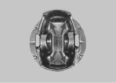
2. Clean the oil drain holes with a suitable piece of wire.
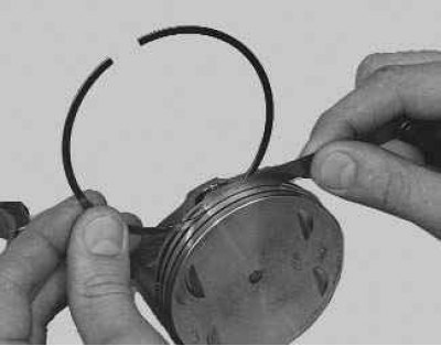
3. Check the gaps between the rings and the grooves on the piston, after cleaning the rings from carbon deposits.
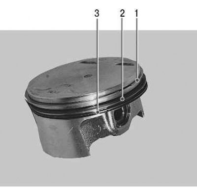
Nominal clearance, mm:
- 0.04–0.075 - upper compression ring 1;
- 0.03–0.065 - lower compression ring 2;
- 0.02–0.055 - oil scraper ring 3.
The maximum permissible gap for all rings is 0.15 mm.
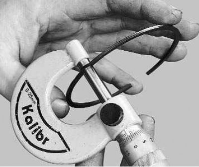
4. The most accurate way to determine clearances is by measuring the rings and grooves on the piston. To do this, use a micrometer to measure the thickness of the rings in several places around the circumference, then use a set of feeler gauges to measure the width of the grooves also in several places around the circumference. Calculate the average gap values (difference between ring thickness and groove width). If at least one of the gaps exceeds the maximum permissible value, replace the piston with rings.
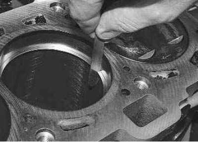
5. Measure the gaps in the ring locks by inserting the ring into a special mandrel. If there is no mandrel, insert the ring into the cylinder in which it was used (or will it work if the ring is new), use the piston as a mandrel to push the ring into the cylinder so that it fits into the cylinder evenly, without distortions, and measure the gap in the ring lock with a feeler gauge. The nominal gap should be 0.25–0.45 mm, the maximum permissible (as a result of wear and tear) – 1.0 mm. If the gap exceeds the maximum permissible value, replace the ring.
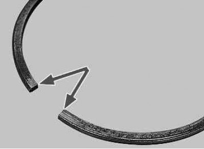
6. If the gap is less than 0.25 mm, carefully file down the ends of the ring.
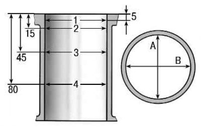
Figure 5.14. Cylinder measurement diagram
7. Measure the diameters of the cylinder in two perpendicular planes (figure 5.14) (B - along, A - across the cylinder block) and in four belts (1, 2, 3 and 4). For this, a special device is required - a bore gauge. Nominal cylinder size (see table 5.1), out-of-roundness and taper must not exceed 0.05 mm. If the maximum wear value is greater than 0.15 mm or out-of-roundness exceeds the specified value, bore the cylinders to the nearest piston repair size, leaving an allowance of 0.03 mm on the diameter for honing. Then hone the cylinders, maintaining a diameter such that when installing the piston, the calculated gap between it and the cylinder is 0.025–0.045 mm. Conduct defect detection, boring and honing of the block in workshops with special equipment.
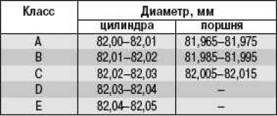
Table 5.1. Nominal dimensions of cylinders and pistons
8. Check the deviation from flatness of the surface of the block joint with the cylinder head. Attach a caliper (or a ruler) to the plane:
- in the middle of the block;
- in the longitudinal and transverse directions;
- along the diagonals of the plane.
[Data obtained from the website LadaMan.ru]
In each position, use a flat feeler gauge to determine the gap between the ruler and the plane. This is a deviation from flatness. If the deviation exceeds 0.1 mm, replace the unit.
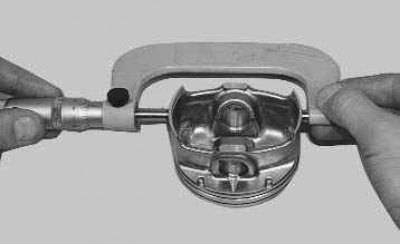
9. Check the clearances between the pistons and cylinders. The clearance is defined as the difference between the measured diameters of the piston and cylinder. The nominal clearance is 0.025–0.045 mm, the maximum allowable is 0.15 mm. If the clearance does not exceed 0.15 mm, pistons from the following classes can be selected so that the clearance is as close to the nominal as possible. If the clearance exceeds 0.15 mm, bore the cylinders and install pistons of the appropriate repair size. Measure the piston diameter at a distance of 10 mm from the lower edge of the skirt in a plane perpendicular to the piston pin.
10. When replacing parts of the connecting rod and piston group, it is necessary to select pistons for cylinders by class and one group by weight, as well as piston pins for pistons by class and connecting rods by weight. To select pistons for cylinders, calculate the gap between them. For ease of selection of pistons for cylinders, they are divided into five classes depending on diameters, each in 0.01 mm: A, B, C, D, E (Table 5.1).
Spare parts are supplied in the form of pistons of nominal sizes of three classes: A, C, E and two repair sizes (1st repair size - increased by 0.4 mm, 2nd - by 0.8 mm).
According to weight, pistons are divided into three groups: normal, increased by 5 g and decreased by 5 g. Pistons of one group must be installed on the engine.
For pistons of repair sizes, rings of repair sizes increased by 0.4 and 0.8 mm are supplied as spare parts. The rings of the 1st repair size are stamped with the number "40", the 2nd - "80".
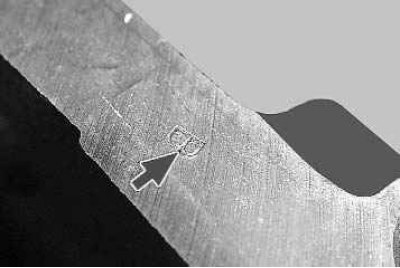
11. Cylinder class designations are stamped on the lower plane of the block (mating surface under the oil pan) opposite each cylinder.
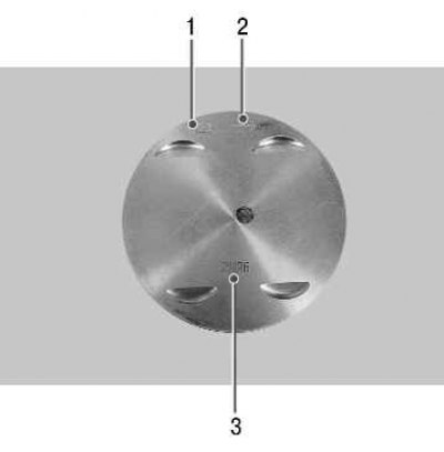
12. The following data is stamped on the piston bottom: 1 – piston class by diameter; 2 – arrow showing the direction of piston installation; 3 – engine model.
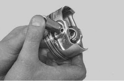
13. Replace cracked fingers. The finger should easily enter the piston with the force of the thumb. Insert your finger into the piston. If there is any play when you wiggle the pin, replace the piston. When replacing a piston, select a pin that matches its class.
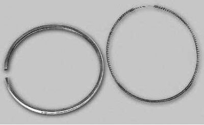
14. Replace broken rings and oil scraper ring expander.
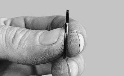
15. Replace broken or cracked piston pin retaining rings. The ends of the retaining rings must be in the same plane. Replace bent rings.
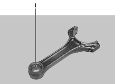
16. Replace bent connecting rods. Replace the connecting rod if there are burrs or deep scratches in the bushing 1 of the upper head. Replace the connecting rod if, when disassembling the engine, it is found that the connecting rod bearings have turned in the connecting rod.
Attention! Connecting rods are processed together with caps, therefore they cannot be disassembled.
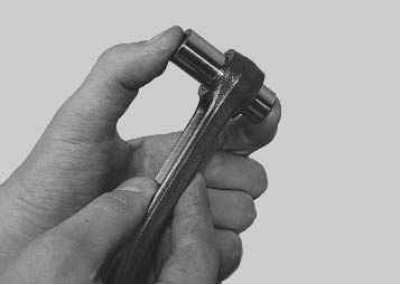
17. Insert the pin into the upper connecting rod head. If there is any play when you wiggle the pin, replace the connecting rod. Connecting rods assembled with caps are divided into classes according to the weight of the upper and lower heads.
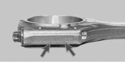
18. The engine must be equipped with connecting rods of the same class. The connecting rod markings are applied to the lower head and the connecting rod cap.
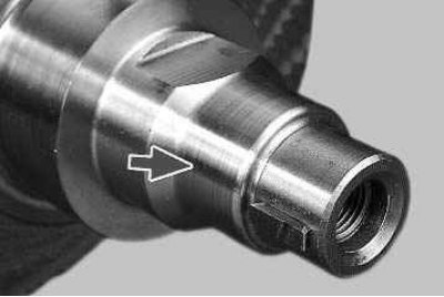
19. If there are deep grooves, scratches, nicks on the surfaces on which the seals operate, the crankshaft must be replaced.
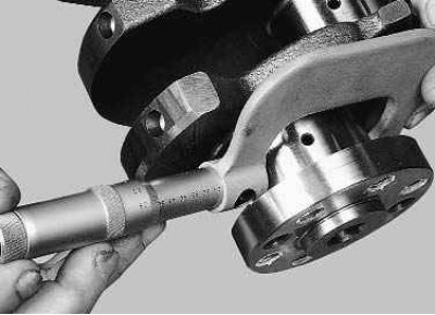
20. Measure the main and connecting rod journals of the crankshaft. Nominal diameters of crankshaft journals, mm:
- indigenous - 50,799–50,819;
- connecting rod - 47.830–47.850.
If the wear or ovality of the journals exceeds 0.03 mm, they must be ground to the nearest repair size.
There are four repair sizes with a reduction in neck diameter, mm:
- first - 0.25;
- second - 0.5;
- third - 0.75;
- fourth - 1.00.
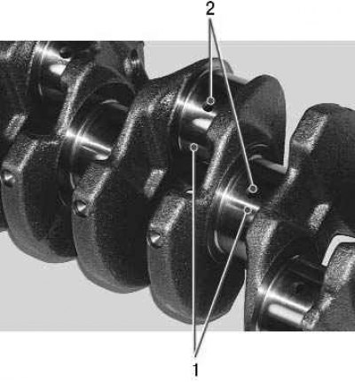
21. If there are minor burrs, scratches or notches on the main and connecting rod journals 1, they must be ground down to the nearest repair size. It is recommended that this work be carried out in a specialized workshop. After grinding, polish the journals and dull the sharp edges of the oil channel chamfers 2 with an abrasive cone. Wash the crankshaft and blow out the oil passages with compressed air. The ovality and taper of all journals after grinding should not exceed 0.005 mm. After grinding the journals, install the liners of repair sizes.
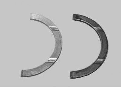
22. If there are burrs, scratches and delaminations on the working surfaces of the thrust half rings, replace the half rings. It is prohibited to carry out any adjustment work on the half rings.
23. Measure the crankshaft axial clearance. To do this, install the crankshaft and thrust half rings in the cylinder block and tighten the main bearing cap bolts (see "Engine assembly").
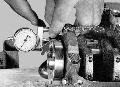
24. Install the indicator so that its leg rests against the shaft flange. Move the crankshaft away from the indicator until it stops and set the indicator arrow to zero. Move the shaft in the opposite direction. The indicator will show the size of the gap. The nominal axial clearance of the crankshaft is 0.06–0.26 mm, the maximum permissible is 0.35 mm. If the clearance exceeds the maximum permissible, replace the thrust half rings.
Spare parts are supplied with thrust half rings of two sizes: nominal – 2.31–2.36 mm and repair (increased by 0.127 mm) – 2.437–2.487 mm.
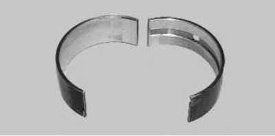
25. Inspect the connecting rod and main bearings. Replace liners with cracks, scuffs, or chipping. It is prohibited to carry out any adjustment work on the liners.
Nominal thickness of liners, mm:
- indigenous - 1.824–1.831;
- connecting rod - 1.723–1.730.
The liners are supplied as spare parts in four repair sizes, with increased thickness, mm:
- the first one is 0.25;
- the second one - by 0.50;
- the third - by 0.75;
- the fourth - by 1.00.
26. Check the clearances between the main bearing shells and the crankshaft journals. It is recommended that this work be carried out in a specialized workshop. Measure the diameters of the journals and main bearings by installing the caps with liners on the block and tightening them to the appropriate torques. Calculate the gap. Clearances between the liners and the crankshaft journals:
- main bearings (nominal 0.026–0.073 mm, maximum allowable 0.15 mm);
- connecting rod bearings (nominal 0.02–0.07 mm, maximum permissible 0.1 mm).
If the clearance exceeds the maximum permissible value, the crankshaft must be ground to the next repair size.
Attention! When re-grinding the connecting rod and main crankshaft necks to the repair size, an appropriate brand must be placed on the first cheek of the crankshaft, for example, W 0.25 and K 0.25, respectively.
27. In a specialized workshop, you can measure the runout of the crankshaft journals.
The runout should be:
- main journals and seating surface for the drive gear of the oil pump no more than 0.03 mm;
- landing surface for flywheel no more than 0.04 mm;
- the seating surface for pulleys and seals is no more than 0.05 mm.
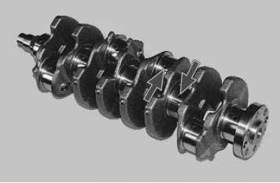
28. Thoroughly clean and flush the crankshaft oil passages.
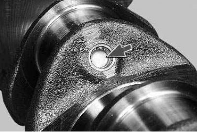
29. It is not recommended to press out the plugs yourself; for this purpose, contact a specialized workshop.
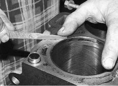
30. Thoroughly clean the cylinder block surfaces from any remaining old sealing gaskets. Inspect the block carefully. If you find cracks, the block must be replaced as an assembly with the main bearing caps.
31. Check the tightness of the cylinder block cooling jacket. To do this, plug the hole for the water pump (installing the pump with a gasket) and pour antifreeze into the cooling jacket. If a leak is visible anywhere, the unit is not sealed and needs to be replaced.
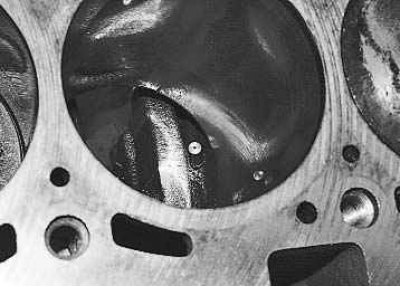
32. Inspect the cylinders. If there are scratches, burrs, cavities and other defects on the cylinder mirror, bore the cylinders to the repair size (it is recommended that this work be carried out in a specialized workshop) or replace the cylinder block. If there are various defects deeper than 0.8 mm, the block cannot be repaired and must be replaced.
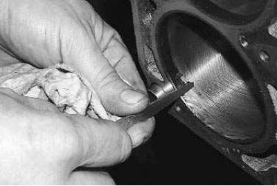
33. Clean the carbon deposits from the top of the cylinders. If a belt has formed there due to wear of the cylinders, remove it with a scraper.
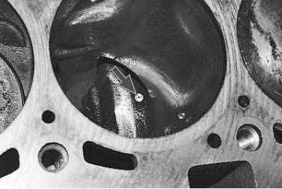
34. Check the presence of nozzles for cooling the piston bottom and the strength of their fit in the holes of the cylinder block beds.