
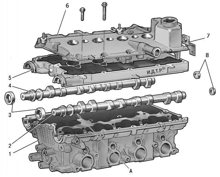
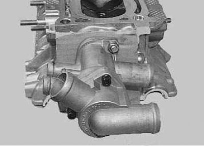
Pic. 5.9. Cylinder Head Details: 1 - block head; 2 – an inlet camshaft; 3 - stuffing box; 4 - final camshaft; 5 – the case of bearings of camshafts; 6 - block head cover; 7 – an arm of fastening of a plait of wires; 8 - plugs; A - a distinctive belt of the intake camshaft
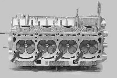
Head 1 (pic. 5.9) cylinder block common to four cylinders, cast from aluminum alloy, with tent-shaped combustion chambers. The inlet and outlet channels are brought to different sides of the block head. The valves are arranged in a V-shape in two rows: inlet on one side, outlet on the other.
Ceramic-metal valve seats and brass valve guides are pressed into the head. Inner diameter of guide sleeves (7±0,015) mm, outer (for bushings supplied as spare parts) - 12.079–12.090 mm and 12.279–12.290 mm (sleeve increased by 0.2 mm).
The diameter of the inlet valve plate is 29 mm, the exhaust valve is 25.5 mm. Inlet valve stem diameter (6,975±0,007) mm, graduation - (6,965±0,007) mm.
Each valve has one spring. Spring length, free 38.19 mm, loaded (240±9,6) H[ (24,5±0,98) kgf] should be 32 mm, and under load (550±27,5) H[ (56,1±2,8) kgf] - 24 mm.
The valves are actuated by the camshaft cams through cylindrical hydraulic pushers located in the guide holes of the cylinder head along the axis of the valve holes. The hydraulic tappets automatically eliminate valve clearance, so there is no need to check and adjust the valve clearance during vehicle maintenance.
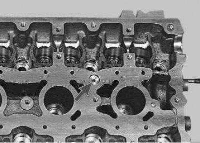
Oil for the operation of the hydraulic pushers is supplied from the lubrication system through a vertical channel in the cylinder block to a channel in the cylinder head near the 5th mounting bolt, and then through the upper channels made on the lower plane of the bearing housing. Oil is also supplied through these channels to lubricate the camshaft journals. A check ball valve is located in the vertical channel of the cylinder head, which prevents oil from draining from the upper channels after the engine is stopped.
The valves are driven by two camshafts: intake and exhaust. The shafts are cast iron and equipped with five bearing journals that rotate in sockets made in the cylinder head and in one common camshaft bearing housing. To increase wear resistance, the working surfaces of the cams and the neck for the stuffing box are bleached. In order to distinguish the intake camshaft from the exhaust camshaft, a distinctive band A is made on the intake shaft near the first bearing.
Shafts are kept from axial movements by thrust collars located on both sides of the front support. The front ends of the camshafts are sealed with self-tightening rubber seals. The rear holes located along the axis of the shafts in the cylinder head and bearing housing are closed with rubberized cap plugs.
You will need: valve spring compressor tool, valve spring press tool and valve stem seal driver, socket wrenches «for 8», «on 10», «at 13», keys «at 19», «at 21», hexagon «on 10», screwdriver, tweezers.
1. Remove the cylinder head from the engine (see «Replacing the cylinder head gasket»).
2. Install the block head with the camshafts up, placing wooden gaskets under it so as not to damage the valves.
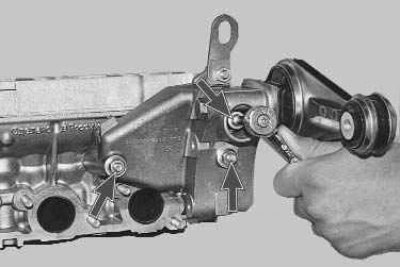
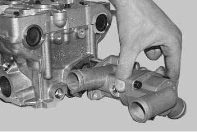
3. Unscrew socket «at 13» three nuts securing the left support of the power unit..
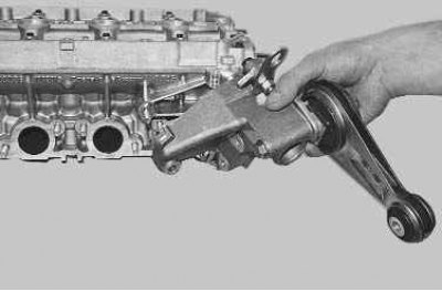
4.... and remove the support.
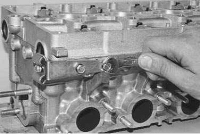
5. Turn out with a key «on 10» two bolts for the fuel pipe bracket..
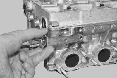
6.... and remove the bracket.
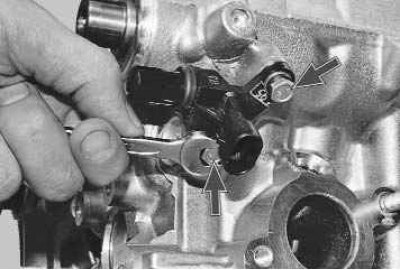
7. Turn out the key «on 10» two bolts for fastening the phase sensor..
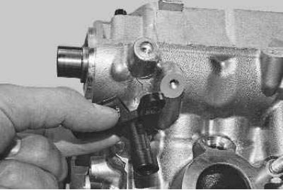
8.... and remove the sensor.
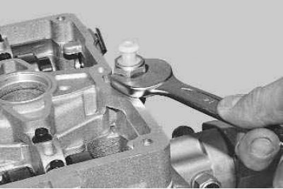
9. Turn out the key «at 21» oil pressure warning light sensor from the camshaft bearing housing.
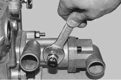
10. Turn out with a key «at 19» from the thermostat coolant temperature sensor.
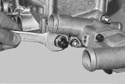
11. Turn out the key «at 21» coolant temperature indicator sensor from the rear end of the block head.
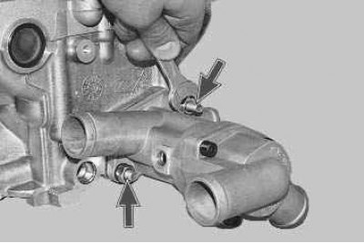
12. Unscrew with a key «at 13» 2 thermostat screws.
13. Remove thermostat..
14.... and the sealing gasket installed under it.
15. Turn out the spark plugs with a candle wrench so as not to accidentally damage them.
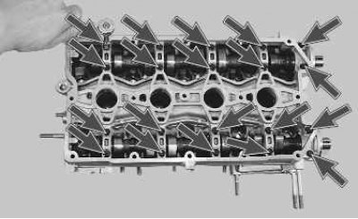
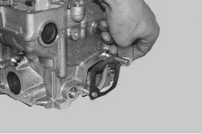
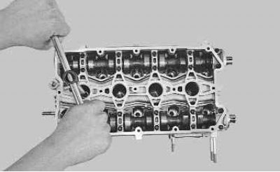
16. Turn out with a socket head «for 8» twenty bolts securing the camshaft bearing housing...
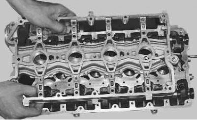
17.... and remove the case.
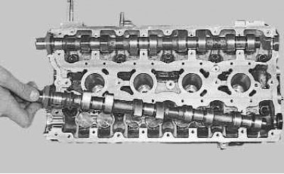
18. Take out camshafts from support of a head of the block of cylinders and remove epiploons from their forward ends.
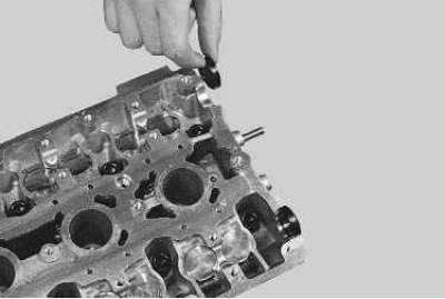
19. Remove the plugs from the rear end of the block head.
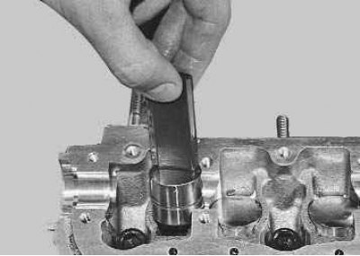
20. Remove the valve lifters from the holes in the cylinder head.
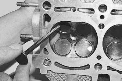
21. Clean the combustion chambers from carbon deposits. Examine the block head. If it has cracks or traces of burnout in the combustion chambers, replace the head. Remove burrs and nicks on the plane of the block head.
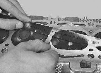
22. Check up flatness of the surface adjoining to the block of cylinders. To do this, place the ruler with an edge on the surface of the head, first in the middle along, and then diagonally, and measure the gap between the surface of the head and the ruler with a feeler gauge. If the gap is greater than 0.1 mm, you can grind the mating surface. To do this, contact a specialized workshop.
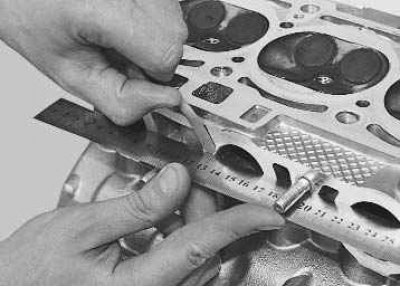
23. Similarly, check the flatness of the mating surfaces of the block head under the intake manifold..
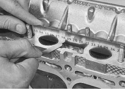
24.... and a collector. The flatness of these surfaces should not exceed 0.1 mm.
25. To check the tightness of the block head, plug the hole in the head under the thermostat socket. This can be done, for example, by installing a blank gasket made of thick cardboard under the socket and tightening the nuts for its fastening. Screw in the sensor of the coolant temperature indicator, if it was turned out.
26. Pour kerosene into the channels of the water jacket. If the level of kerosene drops during exposure for 15-20 minutes, then there are cracks in the head and it must be replaced. After checking, do not forget to remove the cardboard gasket and remove the plugs.
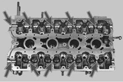
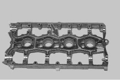
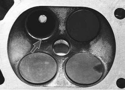
27. Check the condition of the bearing surfaces under the camshaft journals on the block head..
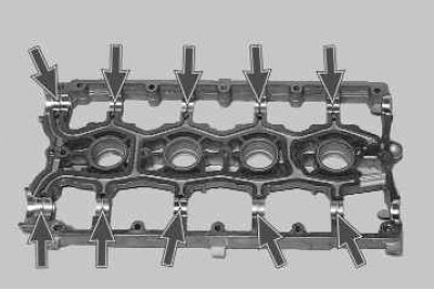
28.... and bearing housing. If at least one of them has signs of wear, scoring or deep scratches, replace the head and bearing housing.
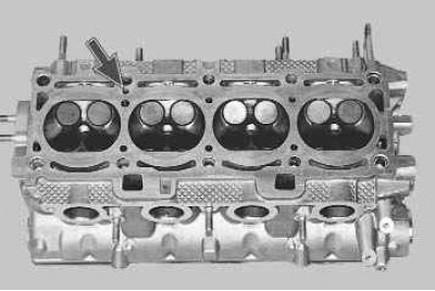
29. Flush the oil passages. To do this, plug the vertical oil passage on the side of the combustion chamber (the channel is located between the 3rd and 4th cylinders)...
30.... pour gasoline into the oil channel of the block head..
31.... and camshaft bearing housings and hold for 15-20 minutes. Pour out gasoline, remove the plug and finally flush the channels with gasoline using a blower.
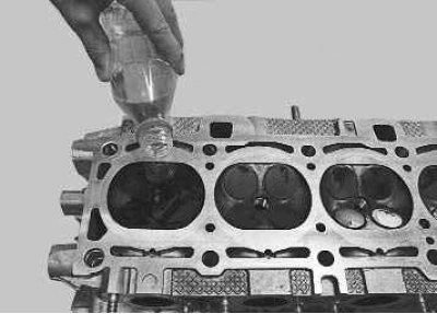
32. To check the tightness of the valves, screw in the candles and pour kerosene into the combustion chambers. If within 3 minutes kerosene does not leak from the combustion chambers into the channels, the valves are tight. Otherwise, rub (see «Lapping of valves») or replace valves.
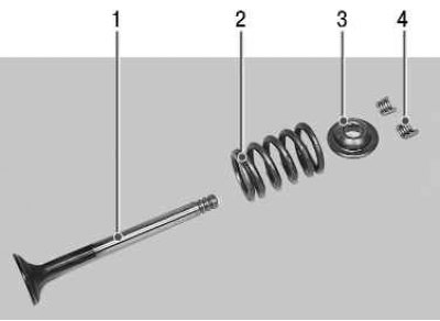
Note. To replace or grind the valves, remove the following parts from the cylinder head: 1 - valve; 2 - spring; 3 - plate; 4 - crackers.
33. Place a suitable stop under the valve to be removed.
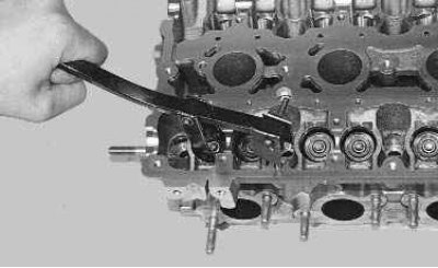
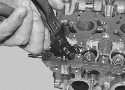
34. Install the valve spring compressor by screwing the camshaft bearing cap bolt into one of the holes in the head of the block and hooking the tool onto this bolt. Compress the valve spring with the tool.
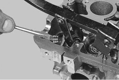
35. Remove two crackers from the upper spring plate with tweezers or a magnetized screwdriver. Then remove the fixture.
Note. If the force of moving the lever of the device increases significantly, and the crackers do not come out of the valve groove, apply a light blow with a hammer on the spring plate so that the crackers are released.
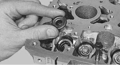
36. Remove the spring plate.
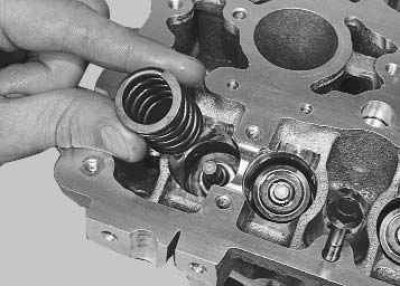
37. Remove the spring.
38. Push and remove the valve from the block head.
39. Press the valve stem seal onto the valve guide with a tool or pliers (see «Replacement of valve stem seals»).
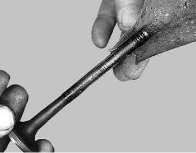
40. Clean carbon deposits from the valve with a suitable tool (e.g. with a metal brush). Then carefully inspect the valve.
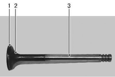
41. Replace valves with the following defects: deep marks and scratches on the working chamfer 1, cracks, deformation of the rod 3, warping of the plate 2, traces of burnout. Shallow risks and scratches on the working chamfer can be removed by lapping the valves (see «Lapping of valves»).
42. If damage to the working chamfer of the valves cannot be removed by grinding, you can grind the chamfer on a special machine in a specialized workshop.
43. Check the condition of the valve seats. Seat faces must be free of wear, pitting, corrosion, etc. The valve seats can be replaced by a specialist workshop. Minor damage (minor scratches, scratches, etc.) can be removed by lapping valves (see «Lapping of valves»).
44. More significant defects in valve seats are eliminated by grinding. Saddles are recommended to be ground in a specialized workshop.
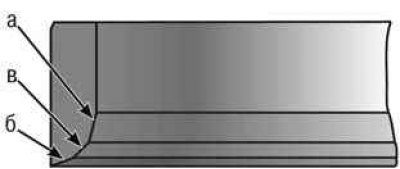
Pic. 5.10. Valve seat bevelling points
45. Having a locksmith skill, this work can be done manually using a set of special cutters. First, chamfer a (pic. 5.10) at an angle of 15°, then chamfer b at an angle of 20°and chamfer at an angle of 45°. After grinding, it is necessary to grind the valves (see «Lapping of valves»).
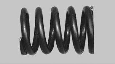
46. Check up a condition of springs of valves. Replace bent, broken or cracked springs.
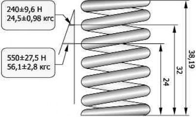
Pic. 5.11. Valve Spring Test Options
47. To check the elasticity of the outer spring, measure its height in a free state, and then under two different loads (pic. 5.11). If the spring does not meet the required parameters, replace it.
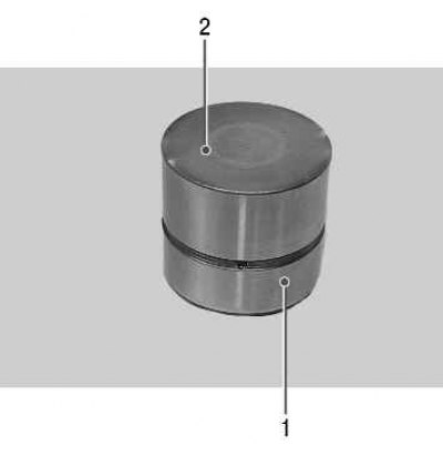
48. Inspect the valve lifters. If there are scuffs, scratches and other defects on the working surface 1, replace the hydraulic pushers. Measure outer diameters of pushers, replace worn pushers. On working surfaces 2 there should be no scuffs, nicks, scratches, traces of stepped or uneven wear, metal rubbing. Hydropushers with such defects must be replaced. On surfaces 2, concentric running-in marks with camshaft cams are allowed.
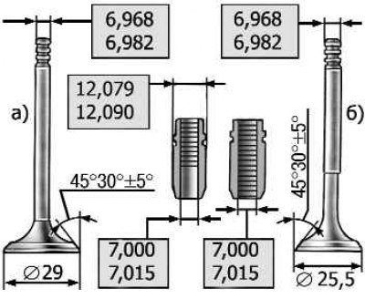
Pic. 5.12. Dimensions of valves and valve guides
49. Check up backlashes between directing plugs and valves. The clearance is calculated as the difference between the diameter of the hole in the sleeve and the diameter of the valve stem (pic. 5.12). It is recommended to check the gap in a specialized workshop, since a special tool is needed to measure the diameter of the bushings (caliper).
Clearances between the valve and the guide sleeve, mm:
- nominal for intake and exhaust valves - 0.018–0.047
- maximum allowable for intake and exhaust valves - 0.300
50. If the gap has not reached the maximum allowable, you can try to eliminate it by replacing the valve. If this fails or the clearance exceeds the limit, replace the guide bushing. To do this, press out the defective bushing from the side of the combustion chamber with a special mandrel, having previously measured the height of the protrusion of the upper part of the bushing above the surface of the block head.
51. Cool the new bushing (e.g. with a carbon dioxide fire extinguisher), lubricate it with engine oil, insert it into a special mandrel and press it in from the side of the camshaft so that the height of the protrusion of the upper part of the bush corresponds to the measured value. Ream the bore in the bushing using a 7.000-7.015 mm reamer for the intake and exhaust valves.
52. If an old valve is being installed, deburr the cracker grooves. After that, it is necessary to grind the valve to the seat (see «Lapping of valves»).
53. Install the valves in the block head in accordance with the previously made markings, after lubricating the rods with engine oil.
54. Install valve stem seals (see «Replacement of valve stem seals»).
55. Install the camshafts and camshaft bearing housing (see «Replacement of valve stem seals»).
56. Install on the head of the block all the parts and assemblies removed during its disassembly.