



You will need: a torque wrench, 13, 17, 19 mm wrenches, 10, 13, 17 mm socket heads, a 10 mm Allen key, and a screwdriver.
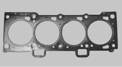
Caution! The cylinder head gasket is a single-use gasket, so it must be replaced each time the cylinder head is removed.
1. Remove the decorative engine cover (see "Removing and installing the decorative engine cover").
2. Set the piston of the 1st cylinder to the TDC position of the compression stroke (see "Setting the piston of the first cylinder to the TDC position of the compression stroke").
3. Reduce the pressure in the fuel system if the work is carried out immediately after driving (see "Loss of fuel pressure in the engine fuel system").
4. Disconnect the wire from the negative terminal of the battery.
5. Drain the coolant (see "Replacing the coolant").
6. Remove the air filter (see "Removing and installing the air filter").
7. Disconnect the heating hoses, small branch of the crankcase ventilation system, purge hose of the adsorber, air supply hose, wiring harness blocks of the throttle position sensor and idle speed control valve from the throttle assembly (see "Removing and installing the throttle assembly").
8. Remove the throttle assembly (see "Removing and installing the throttle assembly").
9. Disconnect the wiring harness connectors from the ignition coils. Remove the ignition coils and remove the spark plugs (see "Replacing and servicing spark plugs").
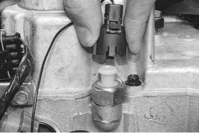
10. Disconnect the wiring harness connector from the oil pressure drop sensor…
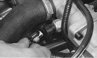
11. …from the engine management system coolant temperature sensor…
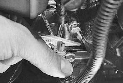
12. …and phase sensor.
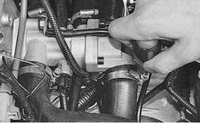
13. Loosen the clamps and disconnect the five cooling system hoses from the thermostat pipes.
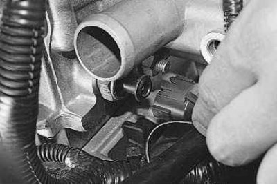
14. Disconnect the wiring harness connector from the coolant temperature gauge sensor.
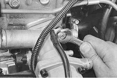
15. Use a 13 mm wrench to loosen the nut securing the ground wire tip…
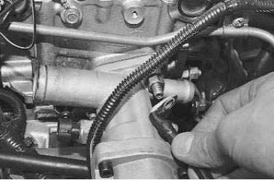
16. …and remove the wire.
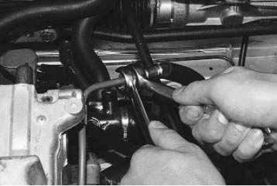
17. Unscrew the fuel hose fitting nut and disconnect it from the fuel line tube.
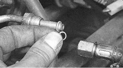
Attention! The tip of the fuel line tube is sealed with a rubber ring. Don't lose it when disassembling. Replace a heavily compressed or torn sealing ring.
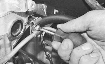
18. Loosen the screw of the pressure plate of the bracket securing the fuel line to the cylinder head and remove the plate.
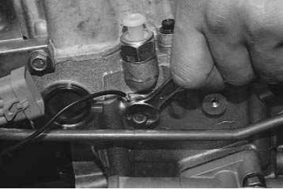
19. Use a 10 mm spanner to unscrew the mounting bolt…
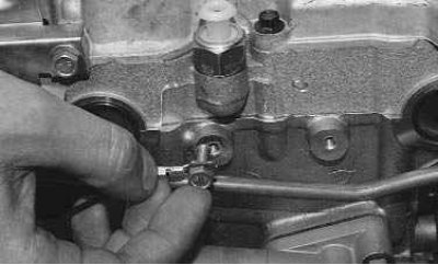
20. …and disconnect the ground wire from the cylinder head.
21. Remove the intake manifold (see "Replacing the cylinder head cover gasket").
22. Remove the cylinder head cover (see "Replacing the cylinder head cover gasket").
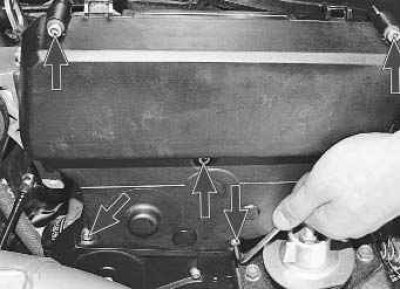
23. Use a 5 mm Allen key to unscrew the mounting bolts and remove the front timing belt cover...
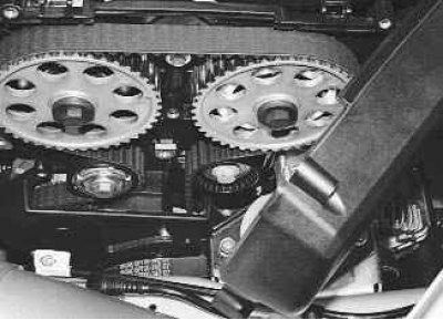
24. …and remove the lid.
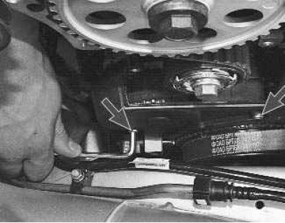
25. Using a 5 mm Allen key, unscrew the bolts securing the lower front timing belt cover…
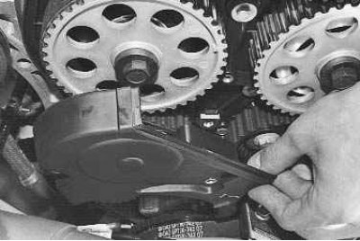
26. …and remove the lid.
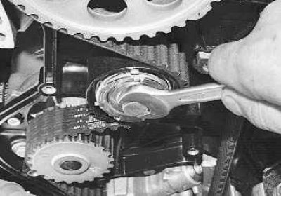
27. Loosen the tension roller mounting bolt with a 15 mm wrench...
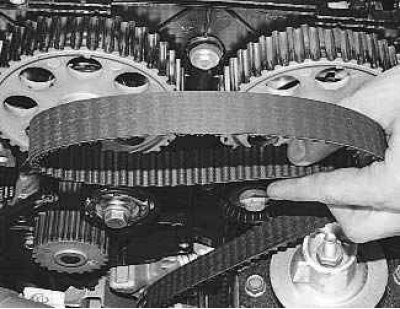
28. ...and remove the timing belt.
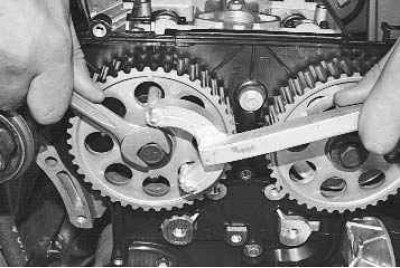
29. While holding the camshaft pulleys from turning, unscrew the pulley mounting bolts…
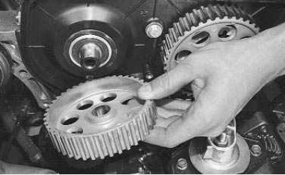
30. …remove the pulleys…
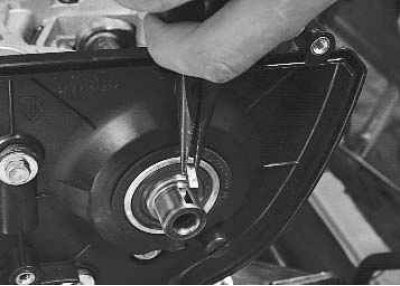
31. …and remove the keys from the grooves of the shaft tails.
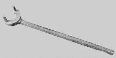
Helpful advice. To prevent the camshafts from turning when unscrewing the camshaft toothed pulley mounting bolts, we recommend using the device shown in the photo.
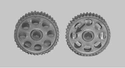
Note: The intake and exhaust camshaft pulleys have the same mounting dimensions, but the intake camshaft pulley has a disc attached to it that ensures the operation of the phase sensor.
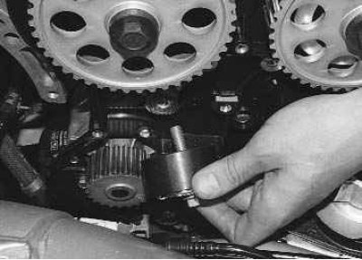
32. Using a 15 mm spanner, unscrew the mounting bolt and remove the tension roller.
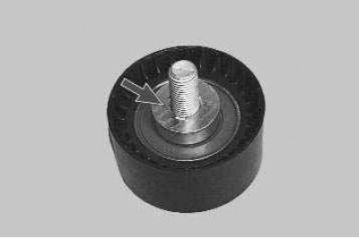
Note: Please note that there is a spacer ring installed under the roller.
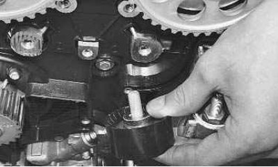
33. Using a 15 mm spanner, unscrew the mounting bolt and remove the support roller.
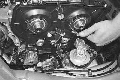
34. Using a 10 mm spanner, unscrew the five bolts securing the rear timing belt cover...
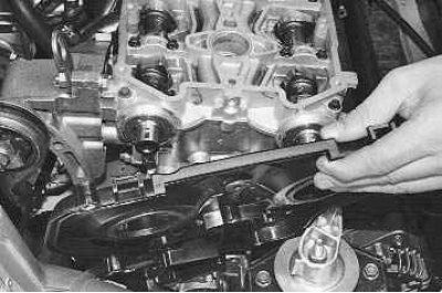
35. ...and remove the lid.
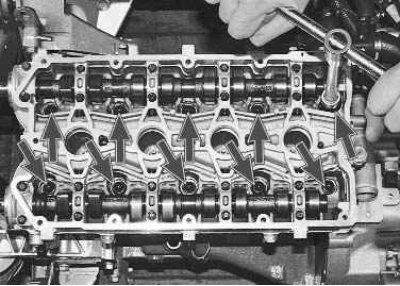
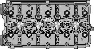
Figure 5.6. Cylinder head bolt tightening sequence
36. Using a 10 mm Allen key, unscrew the cylinder head mounting bolts to the cylinder block in the reverse order of tightening (figure 5.6)...
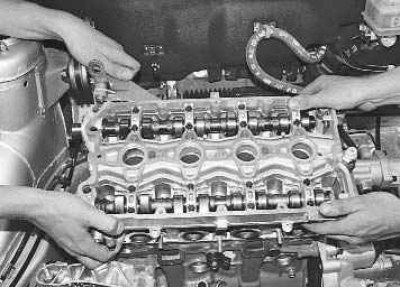
37. ...and remove the cylinder head from the engine.
Caution: Do not jam a screwdriver or other tools between the head and the cylinder block.
Note: It is more convenient to remove the cylinder head with an assistant, as it is quite heavy.
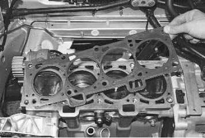
38. Remove the cylinder head gasket.
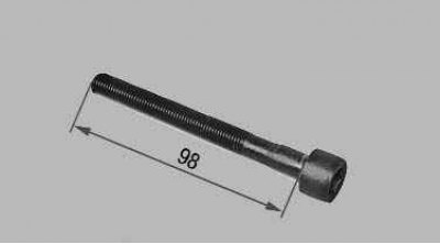
Note: Cylinder head bolts tend to stretch with repeated use. Bolts, the length of which (excluding head height) exceeds 98 mm, replace with new ones. Before installing the cylinder head, lubricate the bolts with a thin layer of engine oil.
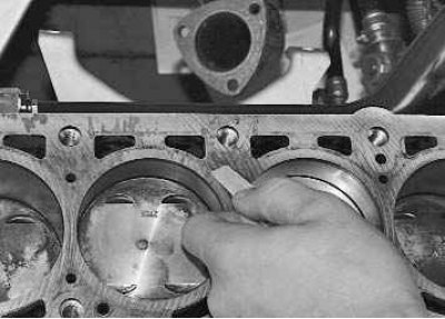
39. Clean the mating surfaces of the cylinder head and cylinder block (they must be dry and clean).
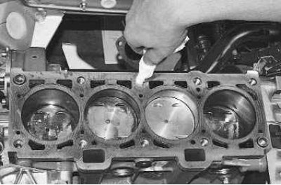
40. Remove oil from the threaded holes in the block under the head mounting bolts.
Caution! If the oil is not removed from the threaded holes for the cylinder head mounting bolts, cracks may appear in the cylinder block when the bolts are tightened, since the oil is not compressed.
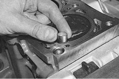
41. Check the presence of two installation bushings in the sockets of the outer holes of the cylinder block for the head mounting bolts. If, when removing the head, the bushings remain in the head or come out of the block sockets, press them into the block until they stop.
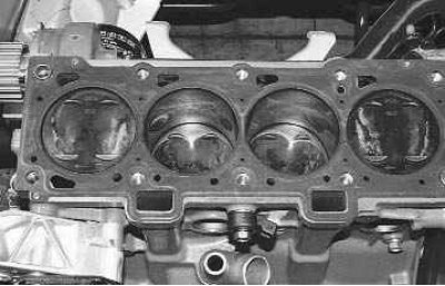
42. Install a new head gasket on the block. The use of a used gasket is not permitted. Before installing the gasket, it is necessary to remove oil from the mating surfaces of the block and its head. The gasket must be clean and dry. Do not allow oil to come into contact with the gasket surface.
43. Install the head on the block, after making sure that the crankshaft and camshafts are in the TDC position (both valves of the 1st cylinder must be closed). Tighten the cylinder head mounting bolts in the sequence shown in the figure 5.6, in four stages:
- 1st - torque 20 N·m (2 kgf·m);
- 2nd - torque 69.4–85.7 Nm (7.1–8.7 kgf·m);
- 3rd - tighten the bolts by 90°;
- 4th - finally tighten the bolts by 90°.
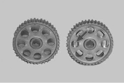
44. Install the removed parts onto the cylinder head and connect the hoses and wires to it in the reverse order of removal. Install the intake camshaft pulley with the disc that ensures the operation of the phase sensor towards the engine. Install the exhaust camshaft pulley in the same manner. Adjust the timing belt tension (see "Replacing the timing belt and tension roller") and the generator drive belt (see "Checking the alternator drive belt tension").
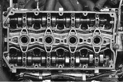
Note. Before installing the cylinder head cover, apply the sealant "Loctayte-574" to the camshaft bearing housing. The engine may not be started earlier than 1 hour after applying the sealant.