



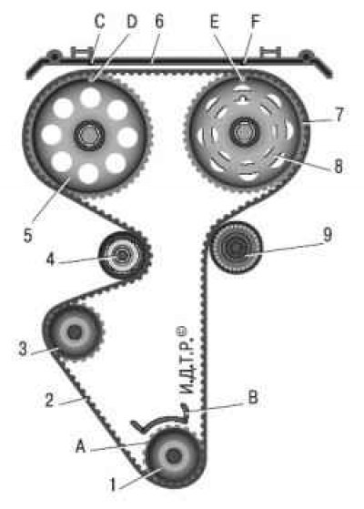
Figure 5.4. Timing drive diagram: 1 – toothed pulley of the crankshaft; 2 – toothed belt; 3 – water pump pulley; 4 – tension roller; 5 – exhaust camshaft pulley; 6 – rear toothed belt protective cover; 7 – intake camshaft pulley; 8 – ring (sync disk) for phase sensor; 9 – support roller; A – TDC mark on the toothed pulley of the crankshaft; B – installation mark on the oil pump cover; C, F – timing marks on the rear protective cover of the toothed belt; D – timing mark on the exhaust camshaft pulley; E – timing mark on the intake camshaft pulley
The camshafts are driven by pulley 1 (figure 5.4) crankshaft by means of a belt drive with a toothed belt. There are two rollers under the camshaft pulleys: tension roller 4 on the left, support roller 9 on the right. The support roller has a mounting hole in the center of the inner race, while the tension roller has an eccentric hole (offset from center by 6 mm). Therefore, by turning the tension roller relative to the mounting bolt, you can adjust the belt tension.
The camshaft pulleys are distinguished by the fact that a synchronization disk 8 is welded to the pulley 7 of the intake camshaft, ensuring the operation of the phase sensor. The drive is covered with plastic covers at the front and back.
To set the valve timing, there are timing marks A, D, E on the pulleys, B on the oil pump cover, and C and F on the rear drive belt cover. When the phases are installed correctly, mark A should coincide with mark B, and marks D and E should coincide with marks C and F.
Replace the camshaft drive belt if, upon inspection, you find:
- traces of oil on any surface of the belt;
- traces of wear on the toothed surface, cracks, cuts, folds and separation of the fabric from the rubber;
- cracks, folds, depressions or bulges on the outer surface of the belt;
- fraying or delamination on the end surfaces of the belt.
You will need: tools to remove the alternator drive belt and the front timing belt cover, a 15 mm spanner, a 17 mm open-end spanner, a special key for turning the tension roller or a snap ring puller, a mounting blade or a large screwdriver.
1. Disconnect the wire from the negative terminal of the battery.
2. Remove the alternator drive belt (see "Replacing the alternator drive belt").
3. Set the piston of the 1st cylinder to the TDC position (see "Setting the piston of the first cylinder to the TDC position of the compression stroke").
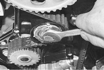
4. Loosen the tension roller mounting bolt with a 15 mm wrench and turn the tension roller to loosen the belt tension.
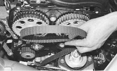
5. Remove the belt from the camshaft pulleys, tension roller and water pump toothed pulley.
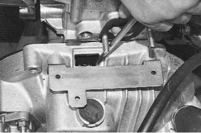
6. In order to unscrew the generator drive pulley mounting bolt, it is necessary to secure the crankshaft from turning. To do this, after removing the plug in the clutch housing, the assistant must use a mounting blade or a large screwdriver to hold the crankshaft by the teeth of the flywheel ring gear.
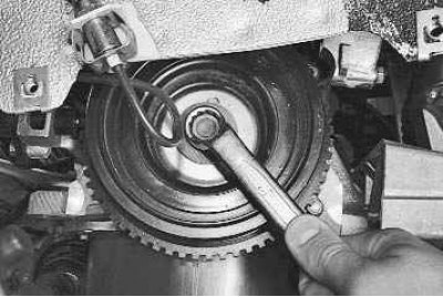
7. Use a 17 mm open-end wrench to unscrew the crankshaft pulley mounting bolt…
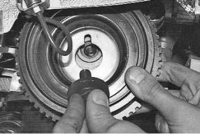
8. … remove it with the washer and remove the generator drive pulley from the crankshaft.
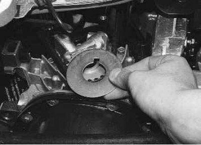
9. Remove the washer from the timing belt drive pulley.
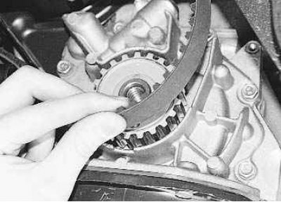
10. Remove the timing belt from the crankshaft toothed pulley.
11. Before installing a new belt, clean the pulleys and tension roller from dirt and grease, degrease them with white spirit.
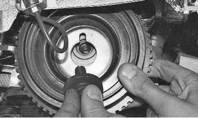
12. Install the camshaft drive belt in the reverse order of removal. The generator drive pulley is installed in only one position. The pulley groove must fit onto the timing pulley lug.
13. When installing the belt, ensure that its leading section is tensioned.
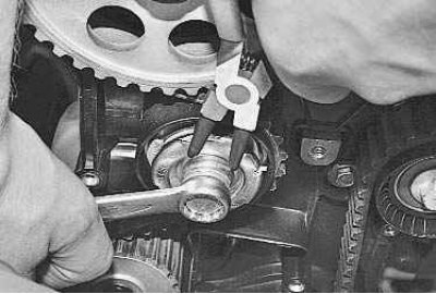
14. After installing the belt, adjust its tension. To do this, use a special key or a snap ring plier inserted into the grooves of the outer disc of the tension roller and turn the roller counterclockwise..
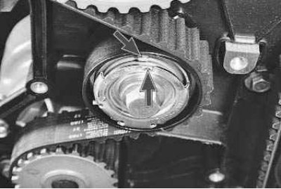
15. …until the cutout on the outer disk is aligned with the rectangular protrusion on the inner sleeve of the tension roller. Tighten the tension roller mounting bolt with a 15 mm wrench to the torque recommended in Appendix 1.
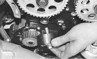
If you hear noise from the camshaft drive belt, there is a chance that the tensioner roller bearing has failed. Remove the roller and check the functionality of its bearing. If you feel binding or axial play when turning the bearing, or if you see signs of grease leaking from the bearing, replace the tension roller.
Article copied from this portal Ladaman.ru
16. To replace the roller, before installing the belt, completely unscrew its mounting bolt and remove the roller.
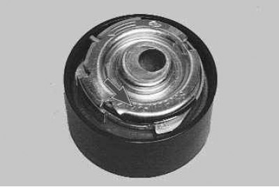
17. Install the new tension roller in the reverse order of removal. In this case, the roller disc with the marking must be directed outward.
18. Adjust the timing belt tension (see paragraphs 13–15).
19. Install all removed parts and assemblies in the reverse order of removal.