



You will need: the tools necessary to remove the gearbox and clutch, as well as a 17 mm socket head and a large screwdriver.
1. Remove the gearbox (see "Removal and installation of the gearbox") and clutch (see "Removing and installing the clutch").
2. Mark the relative positions of the flywheel and crankshaft in any way.
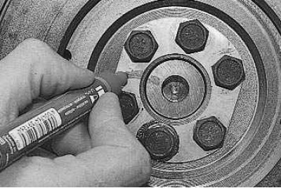
Note: The flywheel should only be installed on the crankshaft in one possible position. To facilitate installation of the flywheel, we recommend marking the relative positions of the parts.
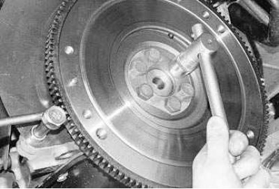
3. Remove the six flywheel mounting bolts. At the same time, use a screwdriver to hold the flywheel from turning, having first screwed in one of the gearbox mounting bolts.
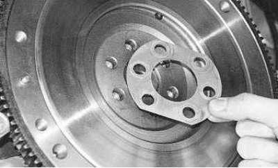
4. After unscrewing the bolts and holding the flywheel, remove the bolt retaining plate.
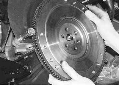
5. Remove the flywheel from the crankshaft flange.
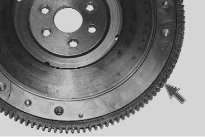
6. Check the condition of the flywheel rim teeth and, if damaged, replace the flywheel.
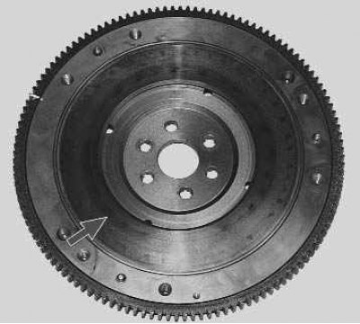
7. Replace or repair the flywheel if there are scratches or scoring on the mating surfaces of the driven clutch disc.
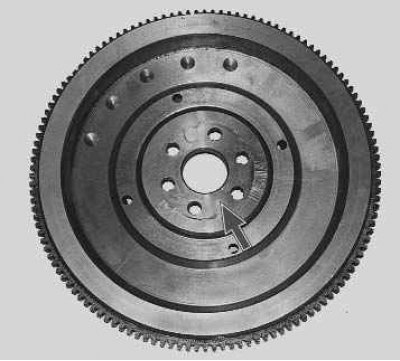
8. If cracks or deep nicks appear on the flywheel flange, replace the flywheel.
The flywheel can be checked and repaired in a workshop with special equipment.
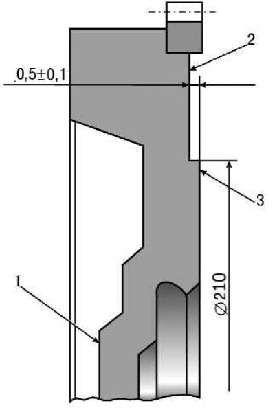
Figure 5.7. Flywheel: 1 – surface adjacent to the crankshaft flange; 2 – place to check the surface for fastening the clutch; 3 – place for checking the runout of the supporting surface of the driven clutch disc
Surface non-flatness 3 (figure 5.7) the contact area of the driven clutch disc should not exceed 0.06 mm.
The non-parallelism of the mating surfaces of the driven clutch disc and surface 2 for fastening the clutch must not exceed 0.1 mm.
The flywheel runout on surfaces 3 and 1 should not exceed 0.1 mm.
To remove deep scratches and burrs, surface 3 of the flywheel can be turned; the thickness of the layer of metal being removed should not exceed 1 mm. At the same time as surface 3, surface 2 must also be turned, maintaining the size between them of (0.5±0.1) mm. When turning, maintain the parallelism of surfaces 3 and 1.
Note: Before installing the flywheel, apply anaerobic thread locker to the threads of the flywheel mounting bolts, having first degreased the bolts and the threaded holes for them.
Install the flywheel in the reverse order of removal, aligning the holes on the flywheel and the crankshaft flange (they are located asymmetrically).