



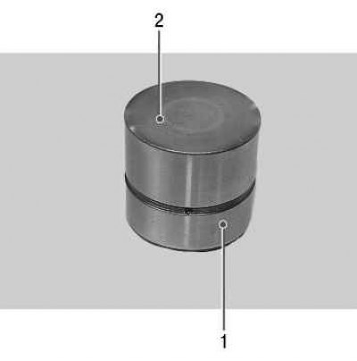
The hydraulic tappets of the VAZ-21126 engine, made in the form of cylindrical tappets located between the camshaft and valves, combine two functions: transmitting force from the camshaft to the valves and eliminating gaps in their drive.
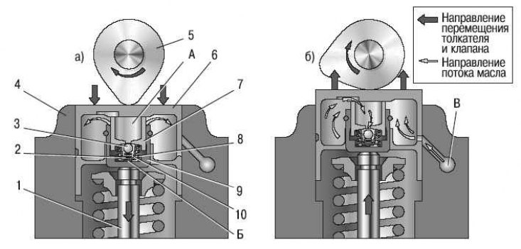
Figure 5.8. Scheme of operation of the hydraulic tappet in the valve mechanism of the VAZ-21126 engine: 1 – valve; 2 – check valve spring; 3 – check valve; 4 – cylinder head; 5 – camshaft cam; 6 – pusher; 7 – plunger; 8 – plunger spring; 9 – sleeve; 10 – check valve body; A, B – hydraulic pusher cavities; B – oil channel
The operation of the hydraulic tappet is based on the principle of incompressibility of engine oil, which constantly fills the internal cavity of the hydraulic tappet during engine operation and moves its plunger when a gap appears in the valve drive. This ensures constant contact between the tappet and the camshaft cam without any gap. This eliminates the need for valve adjustments during maintenance. The operating principle of the hydraulic pusher is shown in the figure 5.8. Oil under the pressure required for the operation of the hydraulic tappet is supplied to the internal cavities A and B from channel B of the engine lubrication system through a side opening in tappet 6, made in the annular groove of its cylindrical surface. With valve 1 closed, pusher 6 (through plunger 7) and the sleeve 9 is pressed by the expanding force of the spring 8, respectively, to the cam 5 of the camshaft and the end of the valve stem. The pressure in cavities A and B is the same, the check valve 3 of the hydraulic tappet is pressed against the seat in the plunger 7 by spring 2 – there are no gaps in the valve mechanism. When the camshaft rotates, cam 5 runs onto tappet 6, moving it and the plunger 7 connected to it. The movement of plunger 7 in sleeve 9 leads to a sharp increase in pressure in cavity B. Despite small oil leaks through the gap between the plunger and the sleeve, tappet 6 and sleeve 9 move as a single unit and open valve 1. With further rotation of the camshaft, cam 5 reduces the pressure on tappet 6 and the oil pressure in cavity B becomes lower than in cavity A. Check valve 3 opens and passes oil from cavity A, connected to the engine oil line, into cavity B. The pressure in cavity B increases, sleeve 9 and plunger 7, moving relative to each other, select the gap in the valve mechanism.
The oil pressure supplied to the hydraulic lifters is regulated by a valve installed in the cylinder head. Since after the engine is stopped, oil flows from the channels coming from the oil pump into the oil sump, and the channels supplying oil to the hydraulic tappets remain filled, air locks may form in the cavities of the latter after the engine is started. To eliminate them, calibration compensation holes are provided in the engine oil supply channels, ensuring automatic purging of the hydraulic tappet cavities. In addition, compensation holes allow to reduce somewhat the pressure of oil entering the hydraulic tappets at high engine crankshaft speed, when the pressure in the cavity of the hydraulic tappet can become so high that its tappet, resting on the back of the camshaft cam, slightly opens the valve at a moment that does not correspond to the valve timing phase.
Almost all hydraulic tappet faults are diagnosed by the characteristic noise emitted by the valve timing mechanism in various engine operating modes.
Valve noise can sometimes be eliminated by slightly turning the spring or valve around the longitudinal axis. To do this, follow these steps:.
1. Turn the crankshaft to the position where the valve making the noise begins to open slightly.
2. Turn the spring a little - the valve will turn at the same time.
3. Start the engine. If the noise persists, repeat steps 1 and 2.
4. If turning the spring and valve does not give the desired result, check the condition of the spring and measure the clearances between the valve stems and guide bushings (see "Disassembly, repair and assembly of the cylinder head"). Eliminate enlarged (compared to nominal) gaps.
If the valve and spring are in good condition, but the valve knocking can still be heard when the engine is running, the hydraulic tappet is faulty. Replace it as follows.
Note: Perform work 20–30 minutes after stopping the engine.
1. Remove the cylinder head cover (see "Replacing the cylinder head cover gasket").
2. Remove the camshafts (see "Replacing the valve stem seals").
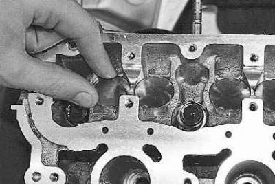
3. To check the hydraulic tappet, press on it. If the hydraulic tappet is in good condition, it should be pushed in with considerable force; if this force is small, the hydraulic tappet is faulty. It is also necessary to check the ease of rotation of the hydraulic tappet in the cylinder head socket. If the hydraulic tappet does not rotate or rotates with great effort, it must be replaced.
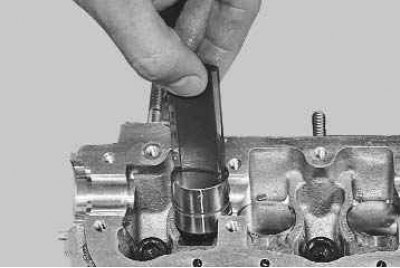
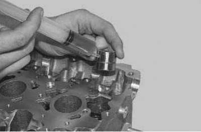
4. Remove the hydraulic tappet from the cylinder head socket.
Note: It is convenient to remove the hydraulic tappet using a magnet of a suitable size.
(Article based on information from the website: «www.ladaman.ru»)
5. Lubricate the new hydraulic tappet and the socket in the cylinder head with engine oil and install the hydraulic tappet into the socket.
6. The remaining hydraulic tappets are replaced in the same way.
7. Install the camshaft and timing drive components in the reverse order of removal.
Note: After replacing the hydraulic tappet, the engine may run with increased noise for a short time during the first start until the hydraulic tappets are bled. To speed up the bleeding of hydraulic tappets, let the engine run at high speed for 1–2 minutes.