
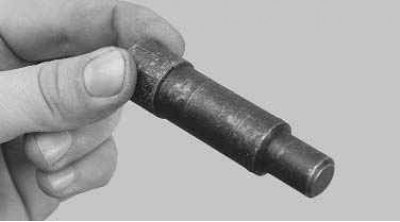
... mandrel for centering the driven disk (can be made from the input shaft of the gearbox by removing the gears).
1. Remove the gearbox (see «Removal and installation of a transmission»).
2. If you install the old pressure plate, mark in any way the relative position of the disc casing and the flywheel in order to install the pressure plate in the same position as before removal (to maintain balance).
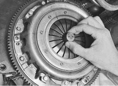
3. Install the mandrel in the pressure plate hole.
Note. You can remove the clutch without a mandrel, but at the same time hold the driven disk: it may fall out of the clutch housing.
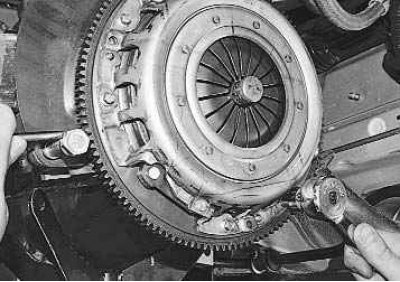
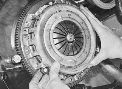
4. While holding the flywheel with a screwdriver from turning, remove the six bolts securing the clutch pressure plate housing to the flywheel. Loosen the bolts evenly: each one turn of the wrench, moving from bolt to bolt in diameter.
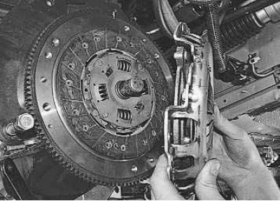
5. Remove the clutch cover assembly with the pressure plate.
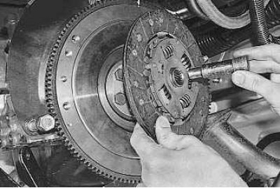
6. Remove the driven disk along with the mandrel.
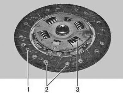
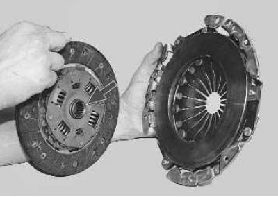
7. Cracks on the parts of the driven disk are not allowed. Check the wear of the friction linings 1. If the rivet heads 2 are less than 0.2 mm deep, the surface of the friction linings is oily or the rivet connections are loose, then the driven disk must be replaced. Check the reliability of fixation of the damper springs 3 in the sockets of the hub of the driven disk; if the springs are broken, the disk must be replaced.
8. Check up beating of a conducted disk if its warping is found out at visual inspection. If the runout is greater than 0.5 mm, replace the disc.
9. Inspect the friction surfaces of the flywheel and pressure plate, paying attention to the absence of deep scratches, scuffs, nicks, obvious signs of wear and overheating. Replace defective units.
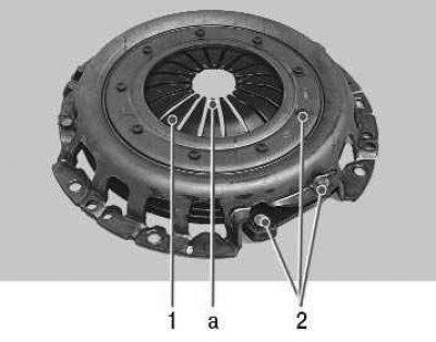
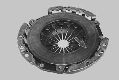
10. Visually assess the condition of the disc spring 1 of the pressure plate. The presence of cracks on the spring is not allowed. Places a of contact between the petals of the spring and the clutch release bearing must be in the same plane and not have obvious signs of wear (wear should not exceed 0.8 mm). Otherwise, replace the pressure plate assembly. If the riveted connections of the 2 parts of the casing and the pressure plate are loose, replace the pressure plate as an assembly.
11. Visually evaluate the condition of the pressure spring support rings. Rings must be free of cracks and signs of wear. Otherwise, replace the pressure plate assembly.
12. Before installing the clutch, check the ease of movement of the driven disk along the splines of the input shaft of the gearbox. If necessary, remove the causes of seizing or replace defective parts.
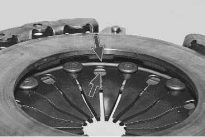
13. Pay attention to the fact that when installing the driven disk in the casing of the pressure plate, the more protruding part of the hub must be directed towards the pressure spring.
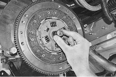
14. When installing the clutch, first install the driven disk using a mandrel...
15.... then the casing of the pressure plate on three centering pins and screw the bolts securing the casing to the flywheel.
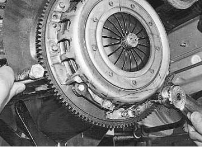
16. Holding the flywheel with a screwdriver from turning, evenly tighten the bolts of the clutch to the flywheel: each one turn of the key, going from bolt to bolt in diameter. The tightening torque of the bolts is specified in appendix 1.
17. Remove the mandrel and install the gearbox.
18. Install the lower end of the clutch release cable to the transmission and restore the original clutch release cable adjustment (see «Replacing the clutch release cable»).
Note. Before restoring the original adjustment of the cable, it is necessary to restore the mechanism for compensating for the wear of the linings of the clutch disc to its original state, since when the clutch disc is completely worn, the wear compensator slider will remain in its lowest position. After installing a new, unworn driven disk, the length of the threaded part of the lower end of the cable may not be enough to restore the initial position of the cable.
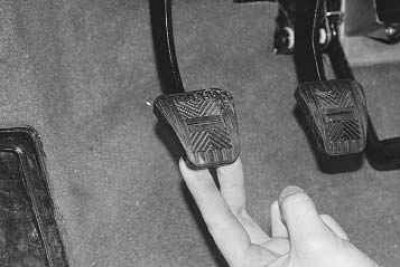
Note. To bring the wear compensation mechanism to its original position by setting the dimension L (see «Replacing the clutch release cable») between the leash and the clutch fork lever, move the clutch pedal up to the stop - the mechanism spring will automatically return the slider to its original position. Then check dimension L again and adjust if necessary.