



- a special template or a wide locksmith's ruler;
- a set of flat probes;
- valve grinding tool;
- rubbing paste.
Examination
1. Remove the cylinder head (see «Cylinder head - removal and installation»).
2. We clean the head of the block and the bearing housing from dirt and carbon deposits, wash it from oil deposits, remove carbon deposits from the walls of the combustion chambers with a metal brush.
3. Carefully inspect the block head and bearing housing. They should not have cracks. On the working surfaces of the camshaft bearings, the bearing housing and the walls of the mounting holes of the hydraulic pushers, there should be no scoring and traces of metal enveloping. The guides and valve seats must fit snugly in the body of the head, with no traces of their displacement during timing operation. Valves and their seats must not have cracks or burn marks.
4. We check the flatness of the cylinder head with a special template.
Comment. If there is no template, then you can check the lower mating plane of the head with a sufficient degree of accuracy using a wide locksmith's ruler. With an edge, we apply a ruler diagonally to the plane of the head. We make sure that there is no gap between the edge of the ruler and the plane of the head. The gap can be observed both in the middle part of the plane and along its edges. We measure the gap along both diagonals with a set of flat probes.
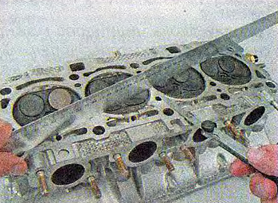
The maximum allowable gap is 0.1 mm.
If the gap is greater than the allowable, the head is subject to milling of the mating plane or replacement.
Warning! The cylinder head should only be replaced complete with bearing housing.
5. Check the tightness of the block head. To do this, on the end surface of the head, we muffle the window for supplying coolant to the thermostat (you can install the thermostat pipe by placing a gasket cut out of sheet rubber under it). We turn the head over and fill its internal cavities for coolant with kerosene.
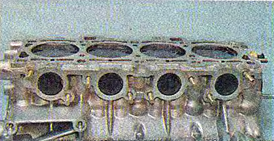
6. We make sure that there is no leakage of kerosene from the block head.
Recommendation. If a leak is found, as well as if shells are found on the mating plane, you can try to repair the block head using cold welding or replace it.
7. To check the tightness of the valves of the block head, lay it on a horizontal surface with the mating plane up.
8. We fill the combustion chambers of the block head with kerosene and wait a few minutes. If the level of kerosene in any chamber drops, then one or both valves are leaking.
Recommendation. Leakage of valves can be eliminated by lapping if there are no cracks, ruts and mechanical damage on the valve disc and seat.
1. Remove the valve stem seal (see «Oil seals - replacement»).
2. Remove the valve from the guide sleeve.
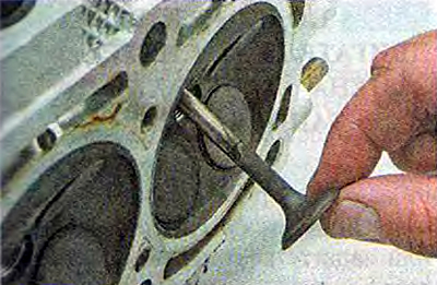
3. Apply lapping paste to the working edge of the valve.
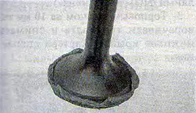
4. We install the valve in the head of the block and fix the device for lapping the valves on its stem.
5. Pressing the valve against the seat, turn it from side to side. After 10-15 strokes turn the valve 90°and continue lapping.
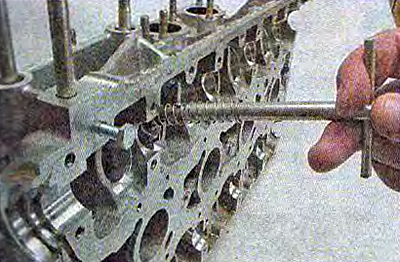
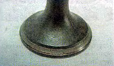
6. Lapping is carried out until a uniform annular rim is formed on the valve disc...
...and his saddle.
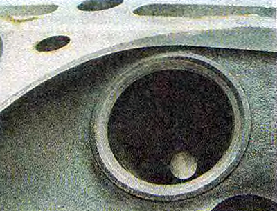
7. Remove the remnants of lapping paste from the valve and its seat.
8. Install the valve in place in the reverse order of removal.
Recommendation. When assembling, install new valve stem seals.
9. Similarly, we grind the remaining valves.