



You will need a piston ring mandrel to get the job done.
Removing
1. Remove the cylinder head (see «Cylinder head - removal and installation»).
2. Remove the engine oil pan (see «Engine oil pan - removal, gasket replacement and installation»)
3. Remove the oil pickup (see «Oil intake - removal and installation»).
4. Turning the crankshaft by the bolt securing its pulley with a 17 mm key, set the piston of the first cylinder to the lower position.
5. Using the TORX E10 wrench, unscrew the two nuts securing the connecting rod cover of the first cylinder.
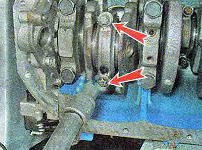
6. Remove the connecting rod cover.
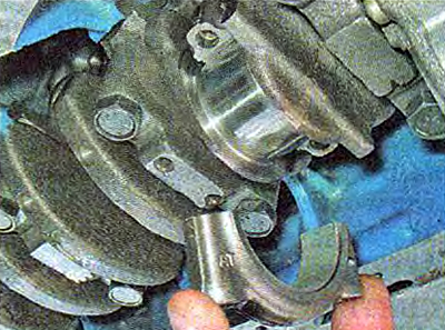
7. Having rested the hammer handle on the piston, we push it up.
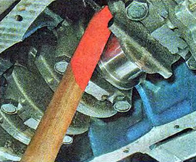
8. Remove the piston from the cylinder.
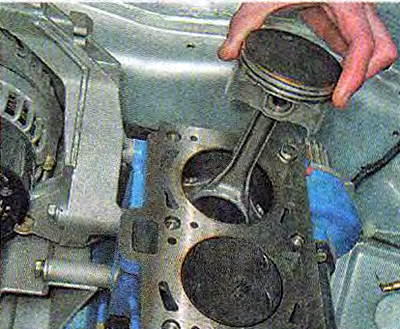
9. We take out loose leaves from a rod and its cover.
10. We fix the piston by the connecting rod in a vice. Slightly spreading the lock of the ring, remove the upper compression ring. Similarly, remove the lower compression ring, oil scraper ring and its expander.
Advice. The rings are thin, and in order not to break them, cut a strip from a plastic bottle a little shorter than the circumference of the piston. Bring the edge of this strip under the lock of the upper compression ring, and then in a circle under the entire ring.
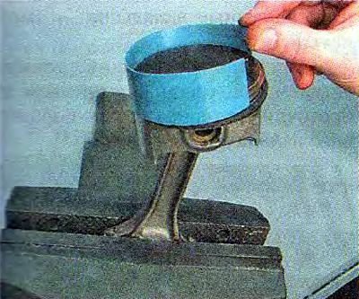
Remove the strip from the piston along with the holz. Remove the second compression and oil scraper ring in the same way.
The expediency of replacing the rings depends on the degree of wear of the cylinders. Small uniform cylinder wear (within 0.05mm) can be compensated by installing a piston of another class with a larger diameter (see «Piston and connecting rod - replacement»).
Installation
1. Thoroughly clean the piston from carbon deposits and deposits. We examine the piston, connecting rod and pin. Cracks are unacceptable.
We select new rings in accordance with the piston diameter - nominal or repair size.
2. Before installing new rings with a set of probes, we measure the gap between the piston ring and the groove wall into which the ring will be installed.
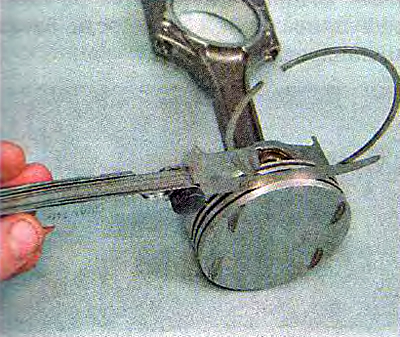
Table 8.1.3. Permissible clearances between groove walls and piston rings

Comment. Permissible clearances between the groove walls and piston rings are indicated in Table. 8.1.3. If the gap exceeds the maximum allowable, the piston must be replaced.
3. To select piston rings according to the thermal gap, we install the rings in turn into the cylinder of the block to a depth of 20-30 mm and determine the gap in the lock with a set of flat probes.
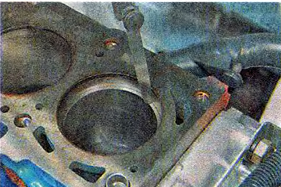
Comment. Maximum allowable thermal clearance during wear (for used rings) - 1 mm, gap for new rings 0.25-0.45 mm. If the gap exceeds the maximum allowable, the ring must be replaced.
4. We put rings on the piston. At the same time, the oil scraper ring...
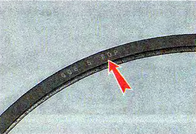
... and install the compression ring with the inscription «TOR» up.
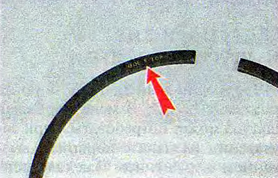
We install new rings on the piston, starting with the oil scraper ring expander.
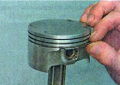
Using a mandrel, we put on the oil scraper ring, and then the lower compression (we put the rings on the mandrel and gently shift down until they are installed in the groove.
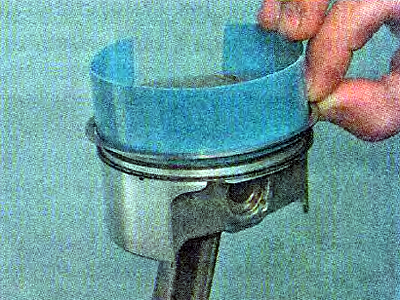
We put on the upper compression ring without a mandrel: by expanding the lock of the ring (no more than is required to put the ring on the piston), we start the lock on the piston first, and then the back of the ring.
5. We turn their locks so that they are located at an angle of 120°relative to each other. The expander lock must be rotated 180°relative to the ring lock.
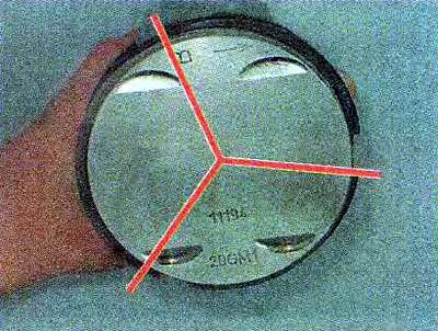
6. Lubricate the cylinder wall with clean engine oil...
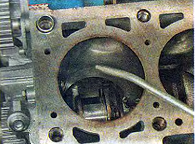
...and the outer surface of the piston.
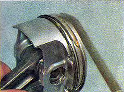
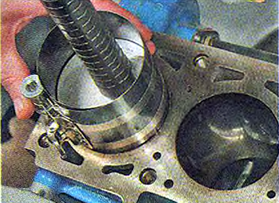
7. We put the mandrel on the piston and crimp the rings with it, periodically tapping the mandrel for self-alignment of the rings with the hammer handle.
Warning! The connecting rod caps are not interchangeable. Installed on the engine «split connecting rods», the covers of which are made by a special method. The contact surfaces of the cap and the connecting rod are uneven, which ensures a perfect fit of the parts during assembly.
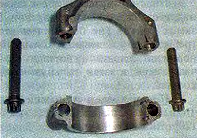
8. We wipe dry the bed liners in the connecting rod and the cover and install the liners in them.
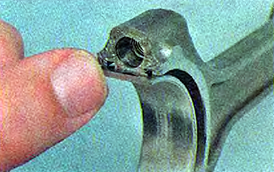
9. Lubricate the inner surface of the liners with clean engine oil.
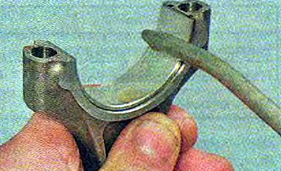
10. Install the piston in the block cylinder.
Warning! The arrow on the piston crown must point towards the crankshaft pulley.
11. Pressing the mandrel against the block and tapping the piston on the bottom of the hammer with a hammer, we sink the piston into the cylinder (at the same time, we control the movement of the connecting rod to the crankshaft journal).
12. We install a cover on the connecting rod and tighten the bolts to a torque of 43.32-53.51 Nm (4.42-5.46 kgf·m).
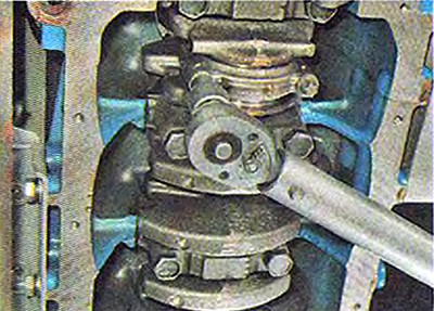
The other three pistons are assembled and installed in the same way.
After installing all the pistons, we assemble the engine in the reverse order of its disassembly.