
You will need a multimeter to do the job.
Removing the steering column switches
1. We prepare the car for work and disconnect the wire terminal from the negative terminal of the battery (see «Car preparation for maintenance and repair»).
2. Remove the decorative lining of the steering column (see «Decorative overlays of a steering column - removal and installation»).
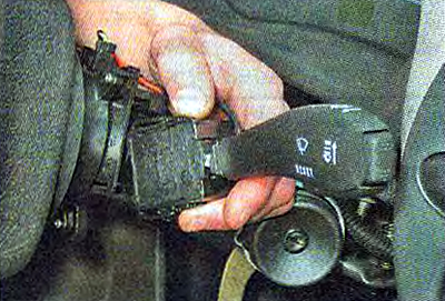
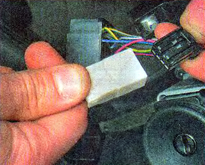
3. Squeezing the spring clips of the right switch, remove it from the connector together with the connected wiring harness block.
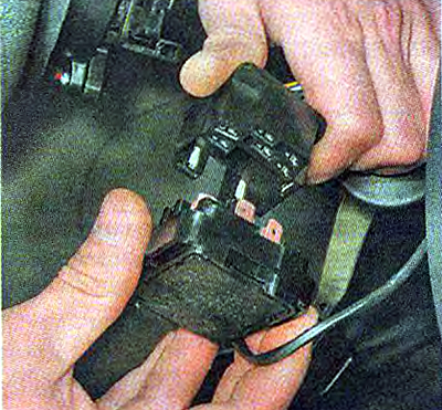
4. Disconnect the wiring harness block from the switch.
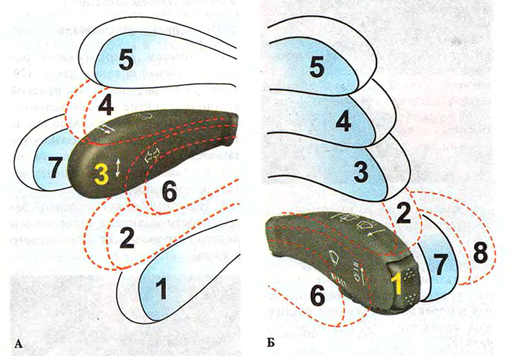
The position of the steering column switches:
A - left steering column switch (headlight and turn signal switch);
B - right stalk switch (wiper and washer switch).
Note. The dotted line shows the positions in which the switch levers are not fixed. Two trip computer control buttons are built into the right switch lever.
Table 13.9.1. Closing of contacts at various positions of levers of understeering switches
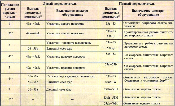
* Pin designations are printed on the switch body.
** Unfixed position.
*** Installed on some cars.
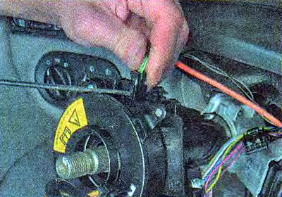
5. Disconnect the block of the wiring harness for the trip computer control buttons.
6. Similarly, remove the left steering column switch.
Examination
With a multimeter in ohmmeter mode, we check the closure of the contacts in the switches at various positions of the switch lever.
Comment. The order of closing contacts at different positions of the switch levers is presented in Table 13.9.1.
Installing paddle shifters
Install switches in reverse order.
Removing the Connector
1. Remove the steering column trim (see «Decorative overlays of a steering column - removal and installation»).
2. Remove the steering wheel (see «Steering wheel - removal and installation»).
3. Remove the steering column switches (see above).
4. On vehicles with a driver's airbag, disconnect the wire block from the contact ring.
Comment. You can remove the connector assembly with the slip ring. If necessary, unscrew the four screws and remove the contact ring from the steering shaft.
Warning! When the steering wheel is removed, the movable part of the slip ring is fixed by a locking mechanism, which prevents it from rotating. Do not press the retainer ring, and rotate the movable part of the slip ring. As a result, during assembly, the central position of the movable part of the ring may be disturbed. In this case, there is a high probability of damage to the slip ring when the steering wheel is turned to one of the extreme positions.
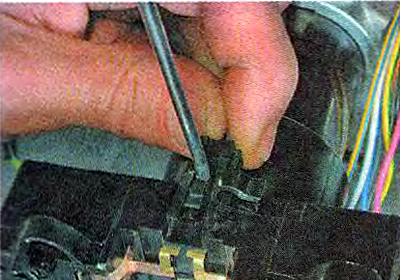
5. Disconnect the block of wires of the sound signal switch.
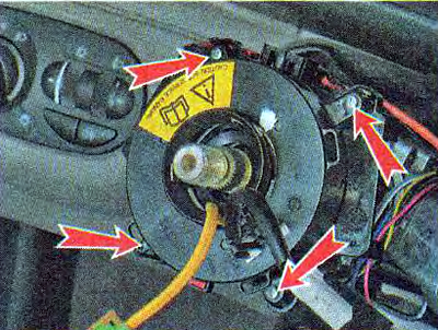
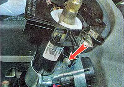
6. Using an 8 mm socket wrench, loosen the bolt securing the steering column switch connector and remove the connector from the steering column.
Connector Installation
1. Install the connector on the steering column.
2. Slightly tighten the coupling bolt of the connector (so that the position of the switch can be changed by hand).
Comment. It is necessary to install the steering column switch connector in such a position that the central screw of the lower steering column trim can be screwed into the corresponding hole in the connector.
3. We install the lower trim of the steering column in place and use a Phillips screwdriver to wrap two screws securing the trim to the cross member of the instrument panel.
4. We adjust the position of the connector on the steering column, achieving the ability to wrap the central screw for fastening the steering column lining into the corresponding hole in the connector.
5. Having found the optimal position of the connector, unscrew the two screws and remove the lower trim of the steering column.
6. Without shifting the connector, we tighten the bolt of its fastening.
7. We carry out further work in the reverse order of removal.