
Note: Switch part numbers see here.
Attention. Removal and installation of understeering switches is made without removal of a steering wheel.
Removing
Put the car on the working place and brake with the parking brake.
Turn the steering wheel towards the switch to be removed and turn off the ignition (the operation is performed to provide access to the screws securing the switch through the upper opening of the steering wheel).
Remove the two screws securing the steering column covers and...
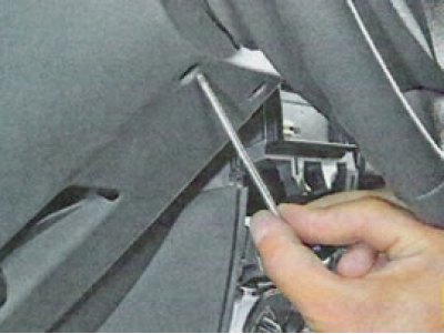
... overcoming the force of the clamps, remove the upper...
... and the lower steering column shrouds.
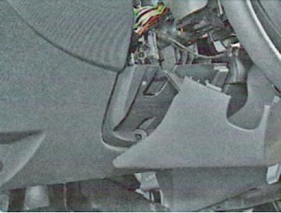
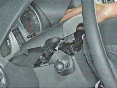
Attention. Before removing the wiper switch, remove the transponder take-up coil from the ignition switch housing.
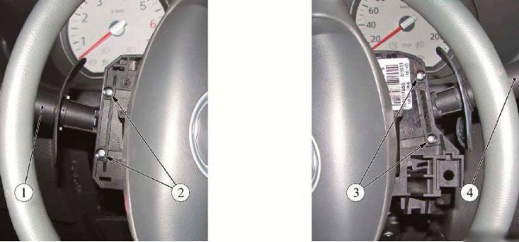
Figure 4-1 - Removing the steering column switches: 1 - switch for direction indicators and headlights; 2 - screws for fastening the switch for direction indicators and headlights; 3 - screws for fastening the wiper mode switch; 4 - wiper mode switch
Loosen two screws (2) left or (3) right, Figure 4-1, fixings, remove the switch (1) or (4) from the switch box.
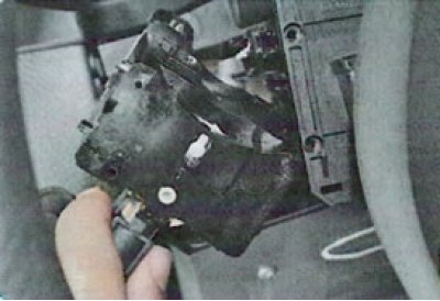
Disconnect the wiring harness from the switch and remove the switch (Phillips screwdriver).
Checking the operation of the steering column switches
Check the correct closure of the switch contacts in various positions. Connect test lamp to 12V (with current source) or autotester with function «dialing» circuits to the corresponding conclusions specified in tab. 1 and 2. Numbers of conclusions of switches are specified on fig. 1 and 2.
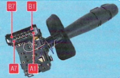
Pic. 1. Pin numbers of the outdoor lighting switch and direction indicators.
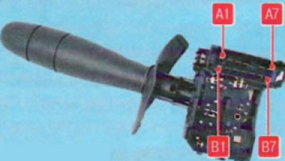
Pic. 2. Wiper and washer switch terminal numbers
Table 1. At various positions of the lever of the switch of external lighting and direction indicators with the button of inclusion of a sound signal
| Device to be switched on | Closed contact numbers |
| Left turn signal | A7-A6 |
| Right direction indicator | A5-A6 |
| marker light | B1-B2 |
| Switching low / high beam | V5-VZ |
| high beam headlights | В5-ВЗ + В7-В6 |
| Front fog lights | A1-B2 + B1-B2 |
| Rear fog lamp | AZ-V2 + V1-V2 |
| Sound signal | A4-B6 |
Table 2. At different positions of the windshield wiper and washer switch lever with the on-board computer display mode switching button
| Device to be switched on | Closed contact numbers |
| Windshield washer pump | A4-B4 |
| Low wiper speed | AZ-A7 |
| High wiper speed | A2-A7 |
| Intermittent wiper operation | A1-A7 + AZ-A6 |
| Intermittent wiper, low speed | AZ-A6 |
| Button for switching on-board computer display modes | A4-B7 |
Move the switch lever to the position corresponding to the contacts being checked - the lamp should light up. Otherwise, the switch is defective.
Installation
Connect the instrument panel harness to the switch.
Install the switch in the switch box housing and secure with two screws (Phillips screwdriver).
Install, if removed, the transponder receiver coil.
Install the upper and lower steering column covers and secure with two screws.
Turn on the ignition and check the operation of the steering column switches.