



The switches are secured in the connector with latches.
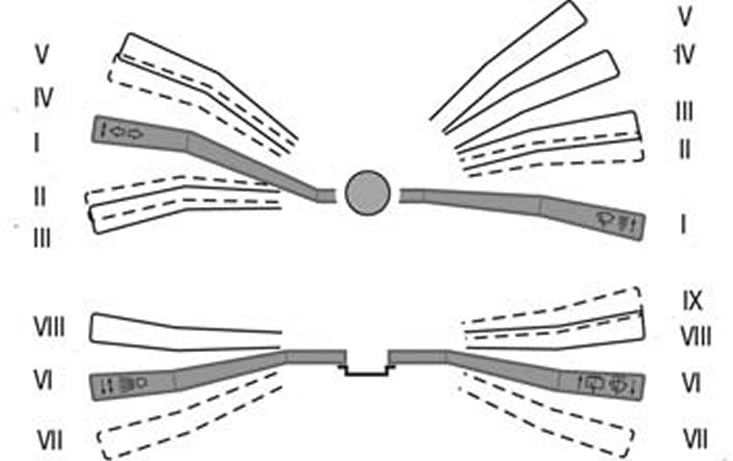
Figure 10.8. Positions of the steering column switch levers
The positions of the switch levers are shown in the figure 10.8, the contacts closed in this case are shown in Table. 10.7.
Table 10.7. Contacts closed at different positions of the steering column switches
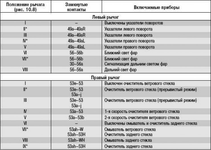
* Non-fixed positions of levers.
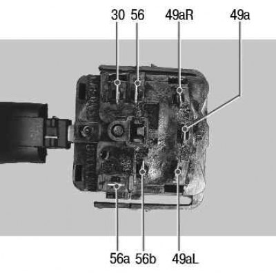
Turn signal and headlight switch contact numbers
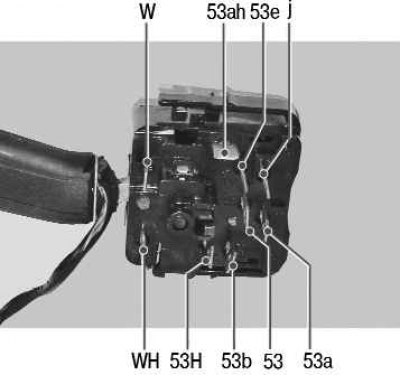
Windscreen Wiper and Washer Switch Contact Numbers
You will need a tester.
1. Disconnect the wire from the negative terminal of the battery.
2. Remove the steering column cover (see "Removing and installing steering column trim covers").
3. Remove the steering wheel (see "Removing and installing the steering wheel").
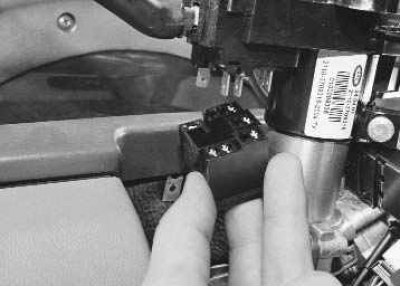
4. Disconnect the connectors with wires from the left steering column switch…
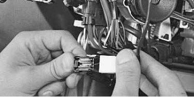
5. …from the trip computer control block…
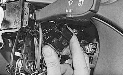
6. …and from the right steering column switch.
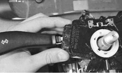
7. Press the plastic clips of the left steering column switch together on both sides…
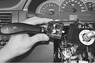
8. …and remove the switch from the connector.
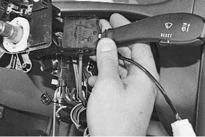
9. Remove the right steering column switch in the same way.
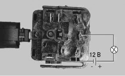
10. To check the switches, connect a 12 V test lamp to the appropriate terminals shown in Table. 10.7 (here is a check of the left turn signal activation). Move the switch lever to the position corresponding to the contacts being tested - the lamp should light up. Otherwise, the switch is faulty.
11. Install the steering column switches in the reverse order of removal.