
Unscrew the two screws securing the steering column covers and, having overcome the force of the clamps, remove the upper and lower steering column covers.
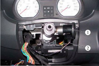
Figure 5-1 - Removing the transponder receiving coil: 1 - transponder receiving coil; 2 - instrument panel wiring harness to transponder receiving coil
Disconnect the instrument panel harness connector from the transponder receiver coil and remove the coil from the ignition switch housing.
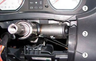
Figure 5-2 - Removing the ignition switch: 1 - screw for fastening the ignition switch; 2 - ignition switch; 3 - clamps
Remove the ignition switch harness connector from the holder on the instrument panel cross member reinforcement.
Disconnect the ignition switch harness connector from the instrument panel harness connector (flat screwdriver).
Remove screw 1, Figure 5-2, securing the ignition switch to the steering column.
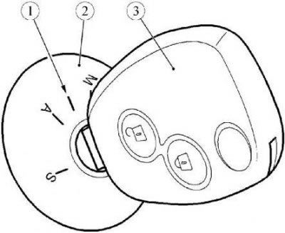
Figure 5-3 - Removing the ignition switch: 1 - key position for removing the ignition switch; 2 - ignition switch; 3 - ignition switch key
Set the key 3, Figure 5-3, the ignition switch to position 1, push in the latches 3, Figure 5-2, and remove the ignition switch 2.
Installation
Attention. Do not reuse the screw that secures the ignition switch to the steering column. The screw must be replaced.
Set the ignition switch key to position 1, Figure 5-3.
Install the ignition switch to the steering column and secure with the screw.
Connect the ignition switch harness connector to the instrument panel harness connector and secure the connectors in the holder on the instrument panel cross member reinforcement.
Install the transponder receiver coil on the ignition switch and connect the instrument panel harness connector to it.
Install the upper and lower steering column covers and secure with two screws.
Connect wire terminal "masses" to the battery.