
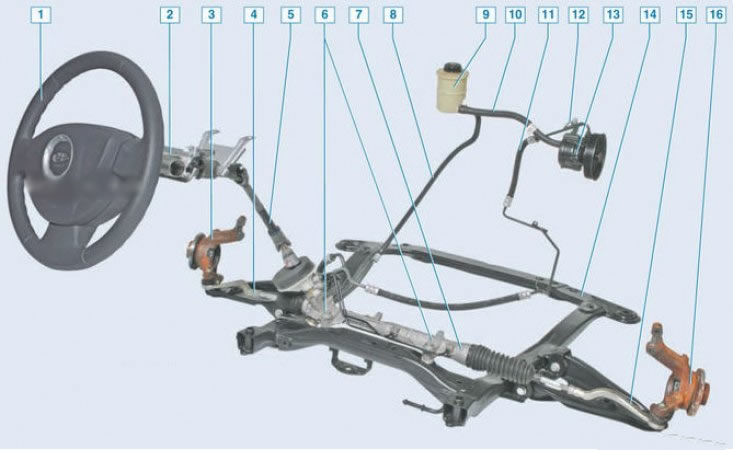
Power Steering: 1 - steering wheel; 2 - steering column; 3 - lion. swivel fist with hub; 4 - lion. tie rod end; 5 - intermediate shaft; 6 – bolts of fastening of the steering mechanism to a stretcher; 7 - crankcase of the steering mechanism; 8 - drain circuit of the hydraulic booster; 9 – a reservoir of a liquid of the hydraulic booster of a steering; 10 - filling circuit of the hydraulic booster; 11 - the discharge circuit of the hydraulic booster; 12 - hydraulic booster fluid pressure sensor; 13 - hydraulic booster pump; 14 - subframe; 15 - etc. tie rod end; 16 - etc. knuckle with hub
The vehicle is equipped with a tilt-adjustable safety steering column and a rack and pinion steering mechanism. Depending on the configuration, the vehicle may be equipped with power steering.
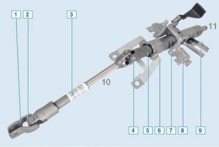
Steering column: 1 - coupling coupling; 2 - lower cardan joint of the intermediate shaft; 3 - the outer part of the intermediate shaft; 4 - upper cardan joint of the intermediate shaft; 5 - steering shaft; 6 - lower steering column mounting bracket; 7 - steering column; 8 - mechanism for adjusting the position of the steering column; 9 - switch (lock) ignition; 10 - the inner part of the intermediate shaft; 11 - splined tip of the steering shaft
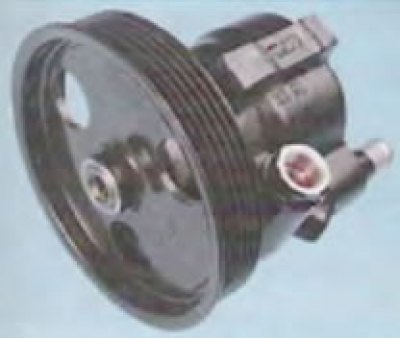
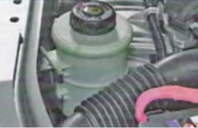
The power steering consists of a hydraulic pump, a power steering gear, low and high pressure pipes and a power steering pump reservoir. The power steering pump is mounted on the accessory mounting bracket, driven by the accessory drive belt.
 |  |
The steering gear is mounted on the front suspension subframe at the lower rear of the engine compartment.
The steering drive consists of two horizontal steering rods and levers on the steering knuckles. The length of each steering trapezoid rod is adjusted by rotating the rod in the outer tip and is fixed with a lock nut.
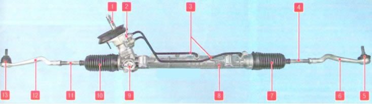
Steering gear: 1 - gear shaft of the steering mechanism; 2 - distribution valve mechanism; 3 - pipelines for supplying the working fluid; 4.11 - steering rods; 5.13 - ball joints of the outer tips of the steering rods; 6, 12 - outer tips of steering rods; 7.10 - protective covers of rods; 8 - steering gear housing, combined with a hydraulic cylinder; 9 - threaded rail stop
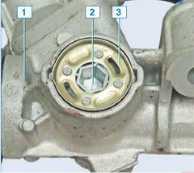
The adjusting plug 2 is fixed on the crankcase of the steering mechanism 1 with the help of a lock washer 3, which is riveted to the plug. The shoulder of the washer is pressed into the grooves of the crankcase in two places.

Tie rod assembly with steering rack: 1 - rail; 2 - ball joint thrust; 3 – steering draft