



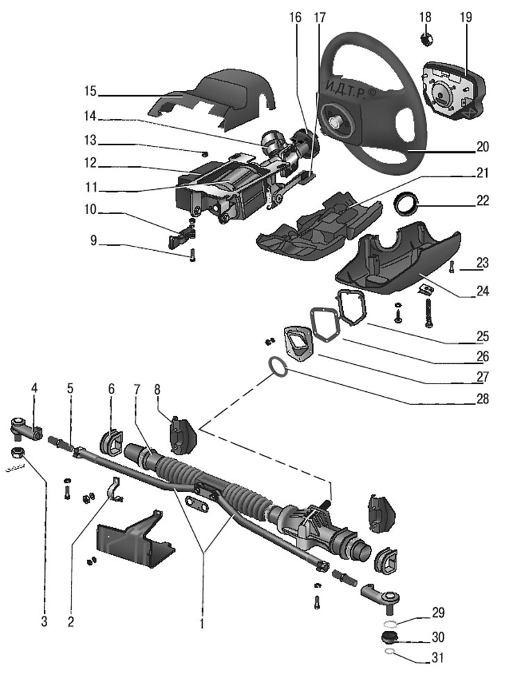
Figure 8.1. Steering: 1 – inner tie rod ends; 2 – steering gear mounting bracket; 3 – steering rod joint nut; 4 – outer tie rod end; 5 – adjusting rod; 6 – steering gear support; 7 – steering mechanism; 8 – steering gear mounting bracket; 9 – tension bolt; 10 – cardan shaft with joint; 11 – Electromechanical power steering; 12 – electronic control unit of the electromechanical amplifier; 13 – steering column mounting nut; 14 – ignition switch; 15 – Upper steering shaft casing; 16 – connector; 17 – steering column adjustment lever; 18 – steering wheel mounting nut; 19 – airbag; 20 – steering wheel; 21 – lower casing insert; 22 – sealing ring; 23 – fastening screw; 24 – lower steering shaft casing; 25 – engine shield fastening element; 26 – gasket; 27 – thrust plate; 28 – seal; 29 – spring ring; 30 – protective cover; 31 – sealing ring
The steering gear assembly with steering rods is attached in the engine compartment to the front body shield on two brackets using clamps 2 (figure 8.1). The mechanism is secured with nuts on welded bolts through rubber supports 6.
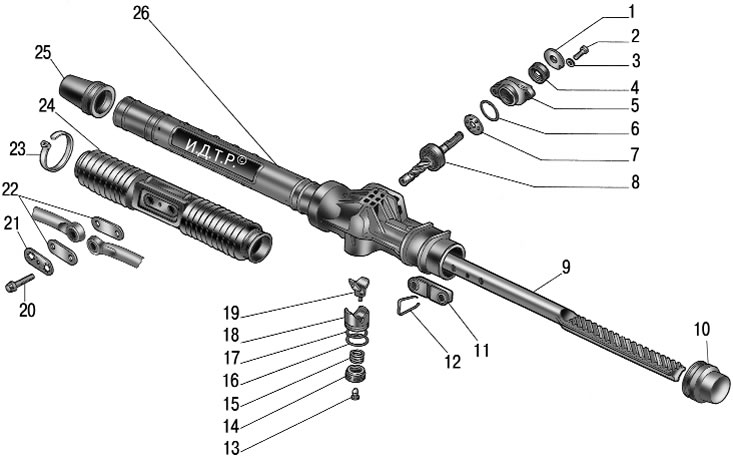
Figure 8.2. Steering mechanism: 1 – anther; 2, 20 – bolts; 3 – washer; 4 – oil seal; 5 – crankcase cover; 6, 17 – sealing rings; 7 – separator assembly; 8 – drive gear with bearing assembly; 9 – steering rack; 10 – left protective cap; 11 – support rods; 12 – bracket; 13 – plug; 14 – stop nut; 15 – stop spring; 16 – retaining ring; 18 – rack stop; 19 – stop insert; 21 – locking plate; 22 – cover plate; 23 – clamp; 24 – protective cover; 25 – right protective cap; 26 – steering gear housing
In the crankcase 26 (figure 8.2) the steering gear has a drive pinion 8 mounted on ball and roller bearings, which is engaged with rack 9. The pinion ball bearing and separator 7 are pressed by cover 5 assembled with seal 4 and are covered by dust cover 1.
The steering gear housing and boot are marked to ensure correct assembly of the steering gear.
Rack 9 is pressed against the teeth of the drive gear by spring 15 through metal-ceramic stop 18, sealed in the crankcase by rubber ring 17. The spring is pressed by nut 14 with locking ring 16, which creates resistance to unscrewing the nut.
A protective cap is put on the steering gear housing on the left side, and a pipe with a longitudinal groove is pressed on the right side; a protective cap is also put on the pipe on the right side. The spacer bushings of the rubber-metal hinges of the inner ends of the steering rods pass through the groove of the pipe and the holes in the protective cover 1 (see figure 8.1). The steering rods are attached to the rack with 20 bolts (see figure 8.2), which pass through the connecting plates 22 and the spacer bushings of the rubber-metal hinges. The bolts are secured with a locking plate 21.
The steering drive consists of two composite steering rods and pivot arms of the telescopic struts of the front suspension. The length of each steering rod is adjusted by rod 5 (see figure 8.1), which is screwed into the inner 1 and outer 4 tips.
Information about malfunctions in the operation of the electric power steering is provided by its electronic control unit when the ignition is turned on by flashing the signal lamp in the instrument cluster (light fault code) (cm. "Electromechanical power steering control unit").