



Removal
Place the vehicle on the work post and apply the parking brake.
Lock the airbag control unit using a diagnostic tool.
Turn off the ignition and disconnect the ground wire terminal from the battery.
Remove the driver airbag module (DABM).
Set the front wheels to a position that corresponds to the straight-ahead movement of the vehicle.
Remove the steering wheel.
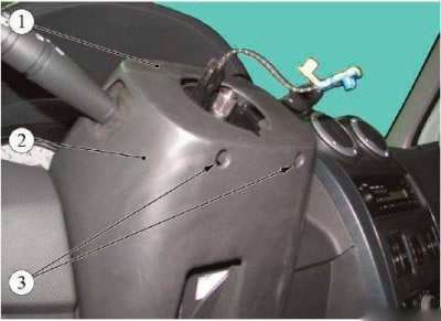
Figure 3-1 - Removing the steering column covers: 1 - Upper steering column cover; 2 - lower steering column cover; 3 - screws for fastening the steering column covers
Unscrew the two screws 3, Figure 3-1, securing the steering column covers and, having overcome the force of the clamps, remove the upper 1 and lower 2 steering column covers.
Attention. Before removing the steering column switch unit with the rotating device, be sure to secure the contact disk of the device by securing its rotating part with adhesive tape, while the front wheels must be in a position corresponding to the straight-line movement of the car.
Loosen screw 4, Figure 3-2, securing block 2 of steering column switches to the steering column housing.
Disconnect the instrument panel wiring harness connectors from the turn signal and headlight switch 1, from the windshield wiper mode switch 7 and from the rotating device 5.
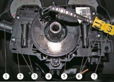
Figure 3-2 - Removing the steering column switch assembly: 1 - direction indicator and headlight switch; 2 - steering column switch block; 3 - screws for fastening the turn signal and headlight switch; 4 - screw for fastening the switch block; 5 - rotating device; 6 - screws for fastening the windshield wiper mode switch; 7 - Windscreen wiper mode switch
Remove the block of 2 steering column switches with a rotating device from the steering column.
If replacement is necessary:
- unscrew the two screws 3 of the fastening and remove the switch 1 of the direction indicators and headlights from the housing of the block 2 of the switches (phillips screwdriver);
- unscrew the two screws 6 of the fastening and remove the switch 7 of the windshield wiper modes from the switch block housing (phillips screwdriver).
Installation
Caution: Re-use of the steering wheel mounting bolt to the steering shaft is not permitted. The bolt must be replaced.
Attention: To avoid damage to the rotating device, install the steering column switch unit under the following conditions:
- the front wheels of the car must be in a position corresponding to the straight-line movement of the car;
- the rotary contact disk of the rotating device must be in the middle position.
Please note: In case of replacement, the new part is supplied with the contact disc in a centred position, secured with an adhesive label that is torn off at the first turn of the steering wheel.
Please note: Some models of rotating devices are equipped with a lock. Before installation, the rotary contact disc must be unlocked.
Adjustment of the rotating device (setting the rotary contact disk to the middle position)
To set the rotary contact disk to the middle position:
- determine the maximum number of revolutions of the contact disk - carefully, without applying force, rotating it from the extreme left to the extreme right position;
- turn the contact disk to the middle position, counting from the extreme position half of the maximum number of revolutions;
- align the marks on the disks.
Adjustment of the rotating device may be performed both on the removed steering column switch unit and on the unit installed on the steering column, immediately before the operation of installing the steering wheel.
If it was removed:
- install the turn signal and headlight switch into the switch block housing and secure with two screws (phillips screwdriver);
- install the windshield wiper mode switch into the switch block housing and secure it with two screws (phillips screwdriver).
Install the steering column switch assembly with the rotating device on the steering column and connect the instrument panel harness pads to the turn signal and headlight switch, to the windshield wiper mode switch and to the rotating device.
Loosen the screw that secures the steering column switch unit.
Install the upper and lower steering column covers and secure with two screws.
Adjust the position of the switch block levers relative to the instrument cluster and finally tighten the screw securing the steering column switch block.
Install the steering wheel.
Install the driver airbag module (DABM).
Connect the ground wire terminal to the battery and turn on the ignition.
Unlock the airbag control unit using a diagnostic tool.
Check the operation of the steering column switches.
Check the operation of the rotating device, for which:
- turn the steering wheel to the extreme left position;
- turn the steering wheel to the extreme right position;
- return the steering wheel to the center position;
- make sure that there is no fault message displayed on the instrument cluster.