



To perform the work you will need an assistant, and it is also desirable to have an inspection ditch.
Recommendation. The work is labor-intensive and requires special equipment and skills. Access to the belt is difficult due to the tight layout in the engine compartment. To remove the timing belt cover, you need to remove the right engine mount, and to do this, the engine must be partially suspended. Therefore, if you are not confident in yourself, have this work done at a specialized service station.
Recommendation. Since a timing belt break can cause collisions between valves and pistons, the timing belt should strictly adhere to the timing belt replacement schedule. When replacing the timing belt, its tensioner and guide rollers should also be replaced.
Removal
1. Prepare the car for work (see "Preparing the car for maintenance and repair").
2. Remove the upper front timing belt cover (see above, "Timing Belt - Checking Condition").
Recommendation. If you are removing the timing belt for purposes other than replacement, use a marker to mark the direction of its rotation. When assembling, it should be installed in accordance with the mark.
3. Remove the front right wheel (see "Wheel replacement") and place the car on a secure stand.
4. Remove the front fender liner from the right side of the car.
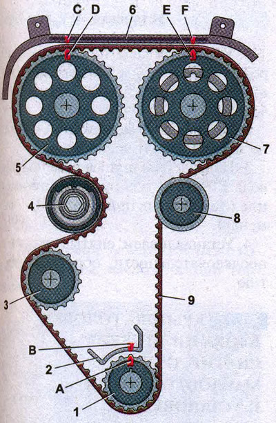
Camshaft drive diagram: 1 - toothed pulley of the engine crankshaft; 2 - lug on the oil pump cover; 3 - toothed pulley of the coolant pump; 4 - tension roller; 5 - toothed pulley of the exhaust camshaft; 6 - rear timing belt cover; 7 - toothed pulley of the intake camshaft; 8 - guide roller; 9 - toothed belt; A - TDC mark on the toothed pulley of the crankshaft; B - mark on the oil pump cover; C, F - mark on the rear timing belt cover; D - mark on the toothed pulley of the exhaust camshaft; E - mark on the toothed pulley of the intake camshaft
5. Remove the generator drive belt (see "Auxiliary Drive Belt - Replacement").
6. Using a 17 mm socket wrench, turn the crankshaft until the marks on the exhaust camshaft pulley align...
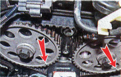
...and on the intake camshaft pulley with marks on the rear timing belt cover. This position will correspond to the position of the crankshaft at TDC of the compression stroke of the first cylinder (see picture).
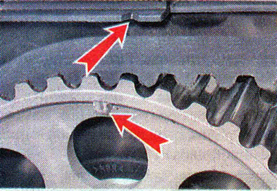
Warning! Do not rotate the timing belt by the camshaft pulley bolts.
1. Using a 17 mm socket wrench with an extension, unscrew the crankshaft pulley mounting bolt.
Note: When performing this operation, the crankshaft can be held by the flywheel ring gear using a slotted screwdriver. To do this, you need to unscrew three screws and remove the starter (see "Starter - removal and installation"), Also, on a car with a manual transmission, the crankshaft pulley bolt can be unscrewed if an assistant engages a higher gear and presses the brake pedal. But the crankshaft may turn slightly. Therefore, it is necessary to re-check that all the marks match.
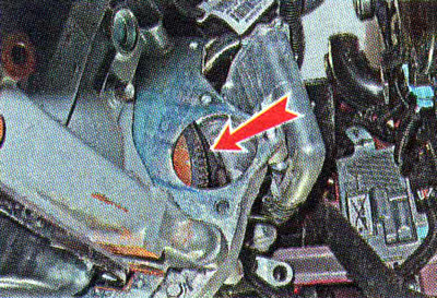
8. Remove the crankshaft pulley and limit washer.
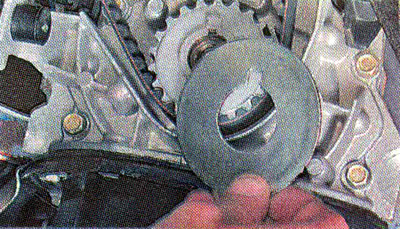
9. Using a 5 mm Allen key, unscrew the three bolts securing the lower front timing belt cover: one on top...
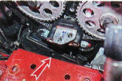
...and two below.
10. Remove the cover.
11. Using a 15 mm wrench, turn the tension roller mounting bolt half a turn counterclockwise to loosen the timing belt tension.
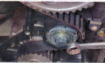
12. Remove the timing belt from the pulleys and remove it from the engine compartment.
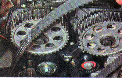
Recommendation. After removing the belt, check the condition of the tension and guide rollers (see below, "Timing belt rollers - replacement").
Installation
1. Put on a new belt, laying its branches in accordance with the drawing (see above), and making sure that the mark on the toothed pulley of the crankshaft is located opposite the lug made on the oil pump housing.
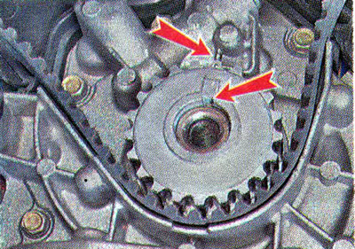
2. Place the belt on the intake camshaft pulley so that the front branch of the belt is taut. Without letting the belt loosen, we put it on the exhaust camshaft pulley.
3. With a snap ring plier (by installing them in the grooves 1) turn the tensioner in the direction of the arrows until the marks 2 on it are aligned...
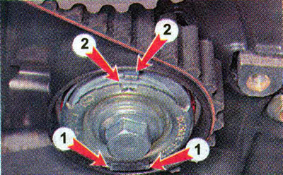
...and using a 15 mm wrench, tighten the tension roller mounting bolt to a torque of 33.2-41.2 Nm (3.4-4.2 kgf·m), shown on a removed engine for clarity.
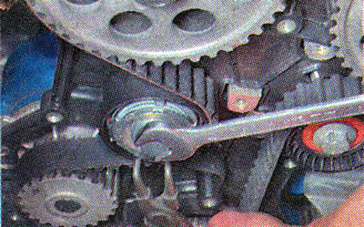
4. If one of the camshafts has turned, then loosen the belt and reinstall it by turning the incorrectly installed camshaft (permissible misalignment of marks within one tooth of the camshaft pulley).
5. Turn the crankshaft two revolutions (by the flywheel crown or by screwing the pulley mounting bolt into the shaft), we make sure that the relative position of the shafts is not disturbed by the coincidence of the marks. If necessary, align the marks and repeat the installation of the belt.
6. After aligning all the marks, install the parts removed from the car back into place.