



Note: You can replace the valve stem seals without removing the head from the cylinder block. To de-compress the valves, you need a compressor and an adapter with a hose to pump air into the cylinder through the spark plug hole. It is possible to de-clamp the valve without using compressed air if the piston is in the highest position (TDC), but it is difficult to install the crackers. To do this, you will need an assistant to use tweezers to lift the valve and hold it in the up position while installing the crackers. Therefore, it is more convenient to perform the work on a removed cylinder head.
To complete the work you will need:
- compressor (developed pressure not less than 2 bar) with a hose;
- adapter for a hose with a thread for a spark plug hole;
- valve spring compressor;
- tweezers;
- valve stem seal remover;
- mandrel for pressing caps.
Removal
1. Turn the crankshaft to the TDC position of the compression stroke of the first cylinder and remove the camshafts (see "Camshafts - Removal and Installation") and fix the crankshaft in this position, engaging the highest gear in the gearbox.
2. With a medical syringe (with a pear or a clean rag) we remove the remaining oil from the cylinder head niches.
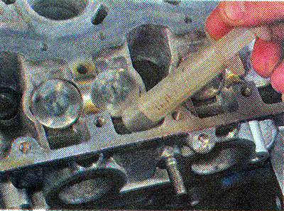
3. Remove the hydraulic tappets from the mounting holes in the head (see "Hydraulic tappets - removal and installation").
4. We screw the adapter into the spark plug hole, connect the compressor hose to it and supply compressed air.
Recommendation. When drying, you can accidentally damage the walls of the hydraulic tappet mounting holes. To prevent this from happening, cut a strip from a plastic bottle and, having rolled it into a ring, install it into the mounting hole of the hydraulic tappet of the valve being disassembled.
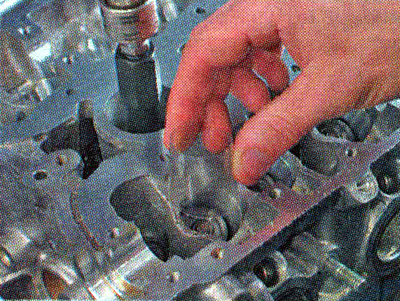
5. Install the valve spring compressor bracket onto the cylinder head.
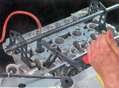
6. Place the valve spring compressor grip under the bolt head and place the stop on the spring plate.
Warning! When performing the following operation, do not scratch the walls of the hydraulic tappet mounting hole with the valve spring compressor!
7. Pressing the valve spring compressor handle, compress the valve spring.
8. Keeping the spring compressed, use tweezers to remove the two valve crackers.
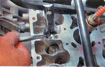
9. Smoothly release the spring and remove the valve spring compressor.
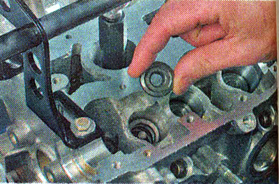
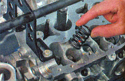
10. Using tweezers, remove the spring plate...
...and remove the spring.
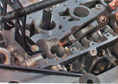
11. Install the puller grip on the oil scraper cap. We press the cap off the valve guide sleeve.
Installation
1. Apply clean engine oil to the working edge of the new valve stem seal and the valve stem.
2. To avoid damaging the working edge of the cap, place a plastic guide mandrel on the valve stem (usually included with new caps) i1 so that it covers the grooves on the rod.
3. Place the oil seal on the valve stem and remove the guide mandrel.
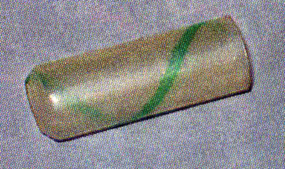
Note: If there is no mandrel, the cap should be put on very carefully so as not to damage it on the sharp edges of the valve stem grooves.
4. Using light hammer blows through the mandrel, press the cap onto the valve guide sleeve.
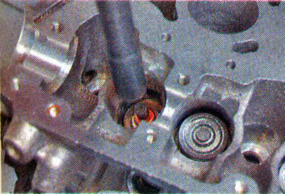
Recommendation. To press the cap on, you can use a 12mm deep twelve-sided socket wrench or an 11mm hexagonal socket wrench.
5. Install the spring, spring plate and crackers in the reverse order of removal.
6. Similarly, replace the oil seals of the remaining valves of the first and fourth cylinders (their pistons are in the TDC position), then we turn the engine crankshaft 180° and replace the valve caps of the second and third cylinders.
7. Install the parts in the reverse order of removal.
[Original publication on the website: LADAMAN]