



Removal
Operations are common for all vehicle configurations
Place the vehicle on a two-post lift, apply the parking brake, turn off the ignition and disconnect the ground wire from the battery.
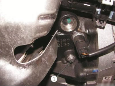
Figure 5-1 - Removing the TDC locking pin hole plug: 1 - plug of the hole for the TDC lock
For cars with K4M engine additionally
Remove the inlet manifold.
Remove the intake silencer.
Operations are common for all vehicle configurations
Remove the engine crankcase guard.
Remove the right front wheel.
Remove the right side mudguard.
Remove the accessory drive belt.
Remove the crankshaft pulley.
Remove the right engine mount.
Unscrew plug 1, figure 5-1, holes for TDC lock (torx E14 socket head, extension, ratchet wrench).
Source link - website www.ladaman.ru
For cars with K7M engine
Unscrew bolts 1, Figure 5-2, securing the upper timing drive cover (replaceable heads 13, 16; ratchet wrench).
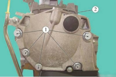
Figure 5-2 - Removing the upper timing cover on the K7M engine: 1 - timing belt drive upper cover mounting bolts; 2 - upper timing belt cover
Remove the upper cover 2 of the timing drive.
Loosen bolts 1, Figure 5-3, securing the lower timing belt cover (replaceable head 8, ratchet wrench).
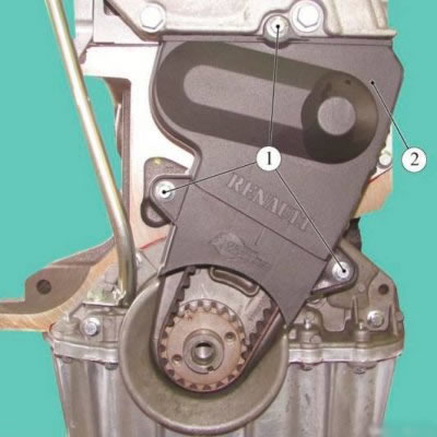
Figure 5-3 - Removing the lower timing belt cover on the K7M engine: 1 - timing belt drive lower cover mounting bolts; 2 - lower timing belt cover
Remove the lower cover 2 of the timing drive.
Tighten the crankshaft pulley mounting bolt with a spacer (replaceable head 18, ratchet).
Turn the crankshaft clockwise so that the mark on the camshaft toothed pulley is one tooth away from the vertical axis of the toothed pulley, and the mark on the crankshaft toothed pulley is one tooth away from the vertical axis of the pulley (replaceable head 18, ratchet).
Install the TDC locking device (tDC locking device Mot. 1489 or 67.7820-9701 L).
Turn the crankshaft clockwise until it stops against the locking device (replaceable head 18, ratchet).
Mark the lid with a marker (marker).
Loosen nut 1, Figure 5-4, securing the tension roller axle (replaceable head 16, ratchet wrench).
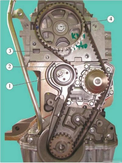
Figure 5-4 - Removing the timing belt on the K7M engine: 1 - tension roller axle mounting nut; 2 - tension roller; 3 - timing belt; 4 - camshaft pulley mounting bolt
Remove timing belt 3. Remove tension roller 2.
For cars with K4M engine
Loosen bolts and nuts 1, Figure 5-5, securing the upper timing belt cover (replaceable heads 13, ratchet wrench).
Remove the upper cover 2 of the timing drive.
Loosen bolts 1, Fig. 5-6, securing the lower timing belt cover (replaceable head 8, ratchet wrench).
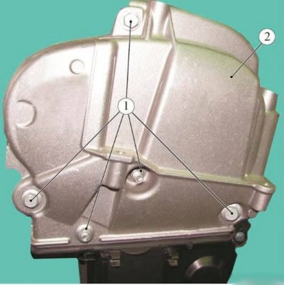
Figure 5-5 - Removing the upper timing cover on the K4M engine: 1 - bolts and nuts for fastening the upper timing belt cover; 2 - upper timing belt cover
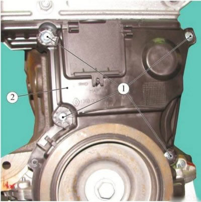
Figure 5-6 - Removing the lower timing belt cover on the K4M engine: 1 - timing belt drive lower cover mounting bolts; 2 - lower timing belt cover
Remove the lower cover 2 of the timing drive.
Loosen the tightening of nut 1, Figure 5-7, securing the tension roller axle (replaceable head 16, ratchet wrench).
Unscrew bolt 5 of the idler pulley mounting using a tool (mot. 1368 fixture, Torx T50 replaceable head, ratchet wrench).
Remove the idler pulley 4.
Remove timing belt 3.
Loosen nut 1 securing the tension roller axle (replaceable head 16, ratchet wrench).
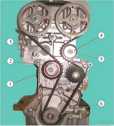
Figure 5-7 - Removing the timing belt on the K4M engine: 1 - tension roller axle mounting nut; 2 - tension roller; 3 - timing belt; 4 - idler pulley; 5 - idler pulley mounting bolt; 6 - toothed pulley of the crankshaft
Remove tension roller 2 of the timing belt. Remove toothed pulley 6 of the crankshaft.
Installation
For cars with K7M engine
Attention. Parts subject to mandatory replacement:
- timing belt;
- timing belt tensioner roller;
- crankshaft pulley mounting bolt.
Install the new tension roller 2 without tightening it, Figure 5-4 (replaceable head 16, ratchet wrench).
Place a new timing belt 3 on the pulleys, aligning the marks on the belt with the marks on the toothed pulleys of the camshaft and crankshaft.
Timing belt installation procedure:
- crankshaft pulley;
- tension roller;
- camshaft toothed pulley;
- toothed pulley of water pump drive.
Timing belt tension on a K7M engine without an automatic tension roller
Install the tension roller until it stops against the timing belt.
Tighten the tension roller axle mounting nut (replaceable head 16, ratchet wrench).
Remove the TDC locking pin (tDC locking device Mot. 1489 or 67.7820-9701 L).
Install device 1, Fig. 5-8, for pre-tensioning the belt on the toothed pulley of the camshaft (mot. 1501 fixture).
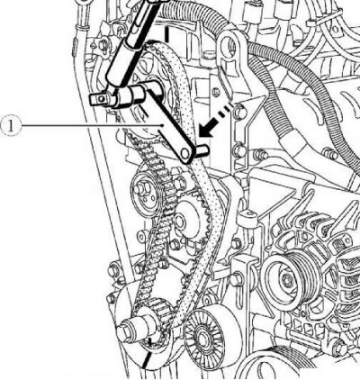
Figure 5-8 - Timing belt tension on the K7M engine: 1 - Mot. 1501 timing belt pre-tensioning device
Create a preliminary tension on the timing belt branch using a torque wrench. The applied force moment is 10 Nm (1.0 kgf·m) (torque wrench).
Remove the tool from the camshaft pulley (mot. 1501 fixture).
Install the timing belt tensioner (device Mot. 1135-01 or 67.7812-9703 L).
Tighten the timing belt by turning the tension roller counterclockwise using the tool (device Mot. 1135-01 or 67.7812-9703 L).
Adjust the timing belt tension by turning the tensioning roller with a tool (device Mot. 1135-01 or 67.7812-9703 L; device Mot. 1505 or "LADAHOPMA - PINAR"). Measure on the timing belt branch between the camshaft pulley and the water pump pulley. Oscillation frequency 160±10 Hz.
Tighten the tension roller mounting nut. Tightening torque 50 Nm (5.0 kgf·m) (replaceable head 16, torque wrench).
Turn the crankshaft two turns clockwise (replacement head 18, ratchet wrench).
Lock the crankshaft in the TDC position using a locking device (tDC locking device Mot. 1489 or 67.7820-9701 L).
Remove the TDC lock.
Install the belt pre-tensioner onto the camshaft sprocket (mot. 1501 fixture).
Create a preliminary tension on the timing belt branch using a torque wrench. The applied force moment is 10 Nm (1.0 kgf·m) (torque wrench).
Remove the tool from the camshaft pulley (mot. 1501 fixture).
Check the tension of the timing belt (device Mot. 1505 or "LADAHOPMA PINAR"). Measure on the timing belt branch between the camshaft pulley and the water pump pulley. Oscillation frequency 160±10 Hz.
If the tension value is outside the tolerance, repeat the timing belt tension adjustment procedure.
Apply FRENETANCHE to bolts 1, Figure 5-2, securing the upper timing belt cover.
Install the upper cover 2 of the timing drive (replaceable heads 13, 16; ratchet wrench).
Tightening torque of the upper timing belt cover mounting bolts:
- m10 bolts - 44 Nm (4.4 kgf·m) (replaceable head 16, torque wrench);
- m8 bolts - 22 Nm (2.2 kgf·m) (replaceable head 13, torque wrench).
Install the lower cover 2, Figure 5-3, of the timing drive (replaceable head 8, ratchet wrench).
Tightening torque of bolts 1 for fastening the lower timing belt cover - 8 Nm (0.8 kgf·m) (replaceable head 8, torque wrench).
Timing belt tension on K7M engine with automatic tension roller
Install the movable pointer 1, Figure 5-9, after the fixed pointer 2, by turning the eccentric 3 counterclockwise using a Torx T50 head key (torx T50 replaceable head, ratchet).
Tighten nut 4 of the tension roller mounting. Tightening torque of the tension roller mounting nut 25 Nm (2.5 kgf·m) (replaceable head 16, torque wrench).
Remove the TDC locking pin (tDC locking device Mot. 1489 or 67.7820-9701 L).
Turn the crankshaft two turns clockwise (replacement head 18, ratchet wrench).
Install the TDC locking device (tDC locking device Mot. 1489 or 67.7820-9701 L).
Turn the crankshaft clockwise until it stops at the TDC lock (replacement head 18, ratchet wrench).
Make sure that the movable pointer 1 is located opposite the fixed pointer 2.
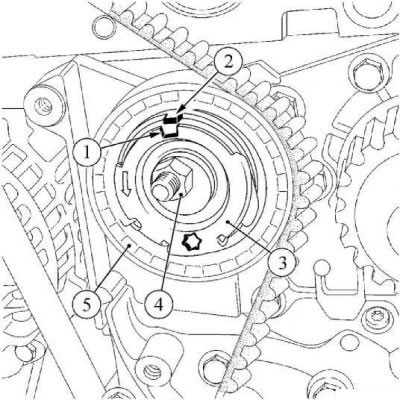
Figure 5-9 - Timing belt tension on a K7M engine with an automatic tension roller: 1 - movable pointer; 2 - fixed pointer; 3 - eccentric; 4 - tension roller fastening nut; 5 - Automatic timing belt tensioner roller
- loosen the timing belt tension roller mounting nut no more than one turn, holding the eccentric with a wrench (replaceable heads 16, Torx T50, ratchet - 2 pcs.);
- smoothly set the movable pointer after the fixed pointer by turning the eccentric counterclockwise using a T50 Torx head key (torx T50 replaceable head, ratchet);
- tighten the tension roller mounting nut. Tightening torque of the tension roller mounting nut 25 Nm (2.5 kgf·m) (replaceable head 16, torque wrench).
Remove the TDC locking pin (tDC locking device Mot. 1489 or 67.7820-9701 L).
For cars with K4M engine
Attention. Parts subject to mandatory replacement:
- timing belt;
- timing Belt Tensioner Roller;
- timing belt idler pulley;
- crankshaft pulley fastening bolt;
- intake camshaft plug;
- exhaust camshaft plug.
Caution: Before installing the crankshaft pulley, degrease the bearing surface of the pulley and the nose of the crankshaft.
If the pointers do not match:
Position the camshaft grooves 1, Figure 5-10, horizontally and offset downwards from the shaft axes, if necessary turning the camshafts using a device (mot. 1496, 16 mm socket, extension, ratchet wrench).
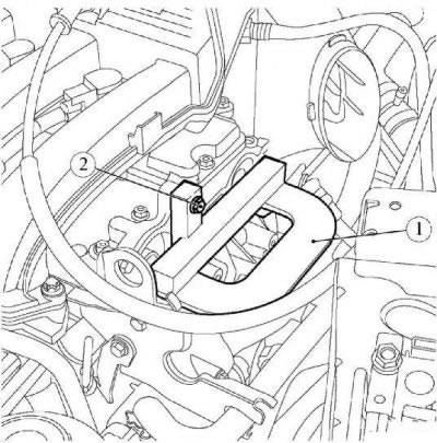
Figure 5-10 - Position of camshaft grooves at TDC: 1 - camshafts
Install device 1, Figure 5-11, for setting the valve timing on the engine and secure with bolt 2 (mot. 1496, replaceable head 10, extension, ratchet).
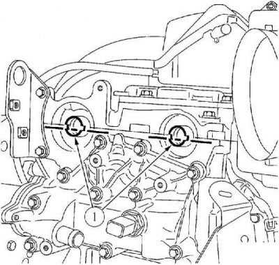
Figure 5-11 - Installing the valve timing tool: 1 - Timing adjustment tools Mot. 1496; 2 - bolt
Place the marks on the spokes of the camshaft toothed pulleys vertically upwards.
Install a new tension roller 2, Figure 5-7, of the timing belt, inserting its protrusion into the groove.
Tighten nut 1 of the tension roller axle without tightening it (replaceable head 16, ratchet wrench).
Install toothed pulley 6 of the crankshaft.
Install a new timing belt 3.
Install a new timing belt idler pulley 4. Tightening torque of bolt 5 securing the timing belt idler pulley - 50 N·m (5.0 kgf·m) (mot. 1368, replaceable head 16, ratchet wrench, torque wrench).
Using a 6 mm Allen key, align the movable pointer A, Figure 5-12, with the recess B of the fixed pointer by turning eccentric 1 clockwise.
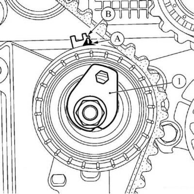
Figure 5-12 - Setting the tension roller marks: 1 - eccentric; A - movable pointer; B - notch of fixed pointer
Tighten the timing belt tension roller mounting nut to 7 N·m (0.7 kgf·m) (replaceable head 16, torque wrench).
Install the lower cover 2, Fig. 5-6, of the timing drive. Tightening torque of bolts 1 securing the lower cover of the timing drive - 12 N·m (1.2 kgf·m) (replaceable head 8, ratchet wrench, torque wrench).
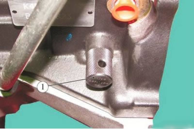
Figure 5-13 - Installing the TDC lock: 1 - TDC lock
Install locking pin 1, figure 5-13, TDC on the cylinder block (tDC locking device Mot. 1489 or 67.7820-9701 L).
Install the crankshaft pulley.
Loosen bolt 2, Fig. 5-11, securing tool Mot. 1496 and remove tool 1 for setting the valve timing (replacement head 10, extension, ratchet).
Remove the TDC lock from the cylinder block (tDC locking device Mot. 1489 or 67.7820-9701 L).
Checking the timing belt tension on the K4M engine
Turn the crankshaft two turns clockwise (if you look from the timing belt side) and until the previously applied marks are aligned (on the phase regulator pulley), install the TDC lock on the cylinder block.
Carefully bring the crankshaft to the stop against the locking device (replacement head 18, ratchet wrench).
Remove the TDC lock from the cylinder block (tDC locking device Mot. 1489 or 67.7820-9701 L).
Make sure that the movable pointer A, Figure 5-12, is positioned opposite the notch B of the fixed pointer, if this is not the case:
- loosen nut 1, figure 5-7, securing the tension roller no more than one turn, holding the movable indicator with a 6 mm Allen key (replaceable head 16, ratchet wrench);
- smoothly move the movable pointer until it aligns with the recess, turning the eccentric clockwise.
Tighten the timing belt tension roller mounting nut to 27 N·m (2.7 kgf·m) (replaceable head 16, torque wrench).
Checking the valve timing on the K4M engine
Before checking the valve timing, make sure that the movable indicator A, Figure 5-12, the tension roller and the recess B of the fixed indicator are in the correct position.
Install locking pin 1, figure 5-13, TDC on the cylinder block (tDC locking device Mot. 1489 or 67.7820-9701 L).
Carefully bring the crankshaft to the stop against the locking device (replacement head 18, ratchet wrench).
Install (without any effort) device 1, figure 5-11, for setting the valve timing (the grooves on the ends of the camshafts 1, Figure 5-10, must be in a horizontal position and be offset downwards from the shaft axes) (mot. 1496 fixture).
If the Mot. 1496 device does not fit into place, then the valve timing must be reset and the timing belt tension adjusted.
Remove the Mot. 1496 timing tool.
Remove the TDC lock from the cylinder block (tDC locking device Mot. 1489 or 67.7820-9701 L).
Install the window cover onto the lower timing cover, making sure the pin fits into the recess.
Operations are common for all vehicle configurations
Apply sealant to the thread of plug 1, Figure 5-1, the hole for the TDC lock and tighten the plug. Tightening torque of the plug 20 Nm (2.0 kgf·m) (torx E14 socket head, extension, ratchet wrench, torque wrench).
Install the right engine mount.
Install the crankshaft pulley.
Install the accessory drive belt.
Install the right side mudguard.
Install the right front wheel.
Install the engine crankcase guard.
For cars with K4M engine additionally
Install the inlet manifold.
Install the intake noise muffler.
Operations are common for all vehicle configurations
Connect the ground wire terminal to the battery.