



Removal
Place the vehicle on a two-post lift, apply the parking brake, turn off the ignition and disconnect the battery ground terminal (electro-hydraulic lift type P-3.2G with lifting capacity of 3.2 t, spanner 10).
Remove the accessory drive belt in accordance with the requirements of Section 4 of this TI.
Remove the crankshaft damper in accordance with the requirements of Section 6 of this TI.
Temporarily install the damper mounting bolt onto the crankshaft (replaceable head 19, ratchet).
Remove the screwdriver installed to lock the engine flywheel from the starter installation hole.
Install crossbar 1 on the vehicle, Figure 7-1, to hang the power unit, insert hook 2 of the crossbar into eye 3 of the right eye and hang the power unit on the right side (crossbar for hanging the power unit).
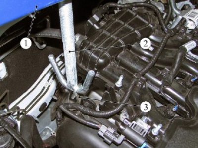
Figure 7-1 - Hanging the power unit: 1 - crossbar for hanging the power unit; 2 - traverse hook; 3 - engine eye
Loosen the two bolts 1, Figure 7-2, securing the power unit to the right support 2 of the power unit suspension (torx E12 replaceable head, extension, ratchet).
Mark the position of the right engine mount support on the body with a marker.
Loosen the two bolts 3 securing the right support of the powertrain suspension to the body and remove the right support (replacement head 16, extension, ratchet).
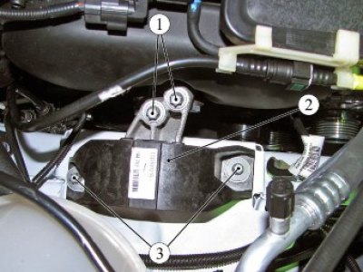
Figure 7-2 - Right powertrain mount: 1 - power unit mounting bolt to the right support; 2 - right support of the power unit suspension; 3 - bolt securing the right support of the powertrain suspension to the body
Unscrew five bolts with washers and remove the front upper protective cover 1, Figure 7-3, of the timing drive (5 mm Allen key).
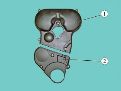
Figure 7-3 - Front Timing Belt Covers: 1 - Front upper timing belt cover; 2 - Front lower timing belt cover
Unscrew three bolts with washers and remove the front lower protective cover 2 of the timing drive (5 mm Allen key).
For cars with engine 21129
Align the timing marks on the timing pulleys by turning the crankshaft by the damper mounting bolt. In this case, the mark on the toothed pulley of the crankshaft should coincide with the mark on the oil pump housing, and the marks on the pulleys of the camshafts should coincide with the marks on the cover of the protective rear (ring spanner 17).
Install the 67.7811-9516 tool on the camshaft pulleys and secure the pulleys (device 67.7811-9516 for fixing camshaft pulleys).
For cars with engine 21179
Align the timing mark on the crankshaft toothed pulley with the mark on the oil pump housing by turning the crankshaft by the damper mounting bolt and install the locking device on the camshaft pulleys (ring spanner 17, device 67.7811-9704 for fixing camshaft pulleys of engine 21179).
Use a marker to make marks on the camshaft pulleys opposite the timing marks on the rear protective cover.
For cars with engines 21129 and 21179
Loosen bolt 1, Figure 7-4, securing automatic tensioner 2 by unscrewing it by 2 - 3 turns, and remove the spacer washer and timing belt 3 from the crankshaft pulley (ring spanner 17, flat screwdriver - 2 pcs.).
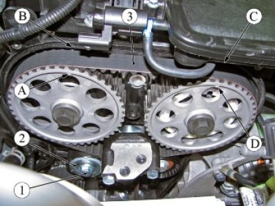
Figure 7-4 - Removing the timing belt on engine 21129: 1 - automatic tensioner mounting bolt; 2 - automatic timing belt tensioner; 3 - timing belt; A, B, C, D - installation marks
Installation
Attention. Adjust and check the tension of the timing belt on a cold engine with a coolant temperature of +15°... +35°C.
For cars with engine 21129
Make sure that the timing marks "A" and "D" on the camshaft pulleys are aligned with the marks "B" and "C" on the rear timing belt cover, as shown in Figure 7-5. If necessary, align the marks and secure the pulleys using tool 67.7811-9516 (device 67.7811-9516 for fixing camshaft pulleys).
Align the timing mark "F" on the crankshaft pulley with the mark "E" on the oil pump cover by turning the crankshaft by the damper mounting bolt in the shortest angular direction (replacement head 17, ratchet, extension).
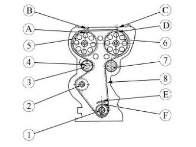
Figure 7-5 - Timing drive parts: 1 - crankshaft pulley; 2 - water pump pulley; 3 - automatic timing belt tensioner; 4 - automatic tensioner mounting bolt; 5 - exhaust camshaft pulley; 6 - intake camshaft pulley; 7 - support roller; 8 - timing belt; A, B, C, D, E, F - installation marks
For cars with engine 21179
Make sure that the "A" and "D" marks on the camshaft pulleys are aligned with the "B" and "C" timing marks on the rear timing belt cover as shown in Figure 7-5. If necessary, align the marks and secure the pulleys using tool 67.7811-9704 (device 67.7811-9704 for fixing the camshaft pulleys of the 21179 engine).
Align the timing mark "F" on the crankshaft pulley with the mark "E" on the oil pump cover by turning the crankshaft by the damper mounting bolt in the shortest angular direction (replacement head 17, ratchet, extension).
[Article based on data from the website: LadaMan.ru]
For cars with engines 21129 and 21179
Tighten bolt 4 of the automatic tensioner with a torque of 5 N·m (0.5 kgf·m) (replaceable head 15, torque wrench).
Install timing belt 8 on pulleys 5 and 6 of the camshafts, support roller 7, automatic tensioner 3, pulley 2 of the water pump and pulley 1 of the crankshaft, as shown in Figure 7-5, maintaining the position of the timing marks on the pulleys.
Install the tension key into the grooves of the support plate of the automatic tensioner 1, Figure 7-6, turn the tensioner counterclockwise to the extreme position until it lightly touches the stoppers of the tensioner lever. Turn the key clockwise until the marks on the automatic tensioner are aligned and tighten the tensioner mounting bolt. Bolt tightening torque 30.36 N·m (3.0...3.6 kgf·m) (key 67.7812.9573-01 for automatic timing belt tensioner, replaceable head 15, torque wrench).
Warning. When tensioning the belt, do not turn the crankshaft by rotating the camshaft pulley.
Remove the camshaft pulley locking device.
Turn the crankshaft two revolutions (ring spanner 17).
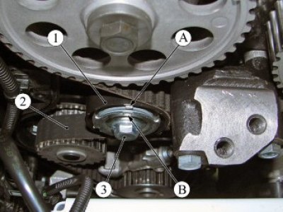
Figure 7-6 - Timing Belt Tension: 1 - automatic timing belt tensioner; 2 - timing belt; 3 - automatic tensioner mounting bolt; A, B - installation marks
If the "A" mark deviates beyond the "B" mark, re-tension the belt, having first unscrewed the automatic tensioner mounting bolt and tightened it with a torque of 5 N·m (0.5 kgf·m) (ring spanners 15, 17; replaceable head 15, torque wrench).
Install a spacer washer onto the crankshaft pulley.
Caution: When installing a timing belt from spare parts, check the condition of the automatic tensioner. If damaged, replace the automatic tensioner.
The performance test of the automatic tensioner must be carried out in accordance with the requirements of TI 3100.25100.40157.
Install the front timing belt drive protective covers one by one, first the lower one 2, Figure 7-3, then the upper one 1, while the upper cover should enter the grooves of the lower cover and dock with it (5 mm Allen key).
Install the right support 2, Figure 7-2, of the power unit suspension on the body.
Install, without tightening, two bolts 1 securing the right support of the power unit suspension to the bracket of the power unit suspension (torx E12 replaceable head, extension, ratchet).
Install, without tightening, two bolts 3 securing the right support of the power unit suspension to the body (replacement head 16, extension, ratchet).
Tighten the two bolts securing the right powertrain suspension support to the powertrain suspension bracket to a torque of 53...71 N·m (5.3...7.1 kgf·m) (torx E12 replaceable head, extension, torque wrench).
Install the right support of the power unit suspension according to the marks on the body made during its removal, and tighten the two bolts securing the right support of the power unit suspension to the body with a torque of 53...71 N·m (5.3...7.1 kgf·m) (replaceable head 16, extension, torque wrench).
Remove hook 2, Figure 7-1, of the crossbar for hanging the power unit from the eye of the right eye 3 on the engine and remove crossbar 1 from the vehicle.
Block the engine flywheel through the starter mounting hole (flat head screwdriver).
Remove the crankshaft damper mounting bolt (ring spanner 17).
Install the crankshaft damper on the crankshaft in accordance with the requirements of Section 6 of this TI.
Install the drive belt of the attachments in accordance with the requirements of Section 4 of this TI.
Install the starter in accordance with the requirements of TI 3100.25100.20597.
Install the engine mudguard in accordance with the requirements of TI 3100.25100.20594.
Install the right inner wheel arch lining in accordance with the requirements of TI 3100.25100.20599.
Install the right front wheel in accordance with the requirements of TI 3100.25100.20594.
Connect the ground wire terminal to the battery in accordance with the requirements of TI 3100.25100.20597.
Present the vehicle to the Quality Control Department. The Quality Control Department will check the vehicle for compliance with the requirements of TU 017200-254-00232934, paragraphs 1.19.5, 1.19.6, 1.19.14.