



Removal
For all vehicle trim levels
Place the vehicle on a two-post lift, apply the parking brake, turn off the ignition and disconnect the battery ground terminal (electro-hydraulic lift type P-3.2G with lifting capacity of 3.2 t, spanner 10).
Remove the right front wheel in accordance with the requirements of TI 3100.25100.20594.
Raise the vehicle to a height convenient for performing the work.
Remove the right inner wheel arch trim in accordance with the requirements of TI 3100.25100.20599.
For cars with H4M engine
Remove the auxiliary drive belt 1, Figure 4-1, by turning the crankshaft damper 2 by the mounting bolt 6 clockwise and guiding the belt with a flat-head screwdriver, carefully, trying not to damage the belt and pulley (flat head screwdriver, replaceable head 19, ratchet).
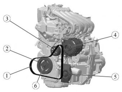
Figure 4-1 - Removing the accessory drive belt on a vehicle with a K4M engine without air conditioning: 1 - auxiliary drive belt; 2 - crankshaft damper; 3 - water pump pulley; 4 - generator pulley; 5 - support roller; 6 - damper mounting bolt
For cars with engines 21129 and 21179
Remove the tension roller plug, loosen nut 1, Figure 4-2, fastenings and move tension roller 2 counterclockwise to the upper position (replaceable head 13, ratchet, Torx T55 bit).

Figure 4-2 - Drive belt for auxiliary units on vehicles with engines 21129 and 21179 and air conditioning: 1 - tension roller fastening nut; 2 - tension roller; 3 - generator pulley; 4 - air conditioning compressor pulley; 5 - drive belt of auxiliary units 6 - crankshaft damper; 7 - damper mounting bolt; 8 - washer
Remove the 5 drive belt for the accessory units.
Installation
For cars with H4M engine
Install mounting tool 67.7834-9703 on damper 2, Fig. 4-1, of the crankshaft (67.7834-9703 tool for installing elastic auxiliary drive belt).
Install belt 1 of the drive of the mounted units on pulley 4 of the generator, place it behind support roller 5 (in the variant version for the air conditioner compressor pulley), pulley 3 of the water pump and put it on the damper 2 of the crankshaft using tool 67.7834-9703.
Rotate the damper by the head of bolt 6 clockwise by % of a turn to put the belt on the damper pulley (ring spanner 19).
Stop the rotation of the damper after releasing the 67.7834-9703 tool from the belt, remove the tool from the damper pulley.
For cars with engines 21129 and 21179
Install belt 5, Figure 4-2, of the drive of the attachment units in the following sequence:
- damper 6 crankshaft;
- pulley 4 air conditioner compressor;
- pulley 3 generator;
- roller 2 tensioner.
Move tension roller 2 to the lower position in a clockwise direction and tighten tension roller mounting nut 1. Nut tightening torque 30.36 N·m (3.0...3.6 kgf·m) (replaceable head 13, Torx T55 bit, ratchet, torque wrench).
Install the tension roller plug.
For all vehicle trim levels
Turn the crankshaft by the damper mounting bolt two turns clockwise to install the belt correctly, make sure that the belt wedges are correctly inserted into the grooves of all pulleys (replaceable head 17 or 19, extension, ratchet).
Install the right inner wheel arch lining in accordance with the requirements of TI 3100.25100.20599.
Install the right front wheel in accordance with the requirements of TI 3100.25100.20594.
Lower the vehicle, install the ground wire terminal on the battery in accordance with the requirements of TI 3100.25100.20597.
Present the vehicle to the Quality Control Department. The Quality Control Department will check the vehicle for compliance with the requirements of TU 017200-254-00232934, paragraphs 1.19.5, 1.19.6, 1.19.14 in the scope of work performed.