



Features of the device
Exhaust gases are discharged from the engine through the exhaust manifold and the exhaust system, which includes a catalytic converter 1, Figure 9-1, an additional muffler 2 and a main muffler 3. The exhaust system is made as a single welded structure, which is suspended from the car body using two rubber cushions. It is possible to replace individual units of the exhaust system using cutting of pipelines and subsequent assembly using repair clamp couplings. For this purpose, the exhaust system is provided with two zones A and B for cutting. On the catalytic converter side, the exhaust system is bolted to the exhaust manifold with a flange.
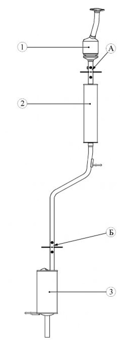
Figure 9-1 - Exhaust system of a vehicle with an H4M engine: 1 - catalytic converter; 2 - additional muffler; 3 - main muffler; A - cutting zone; B - cutting zone
Removal
Place the vehicle on a two-post lift, apply the parking brake, turn off the ignition and disconnect the battery ground terminal (electro-hydraulic lift type P-3.2G with lifting capacity of 3.2 t, spanner 10).
Removal the catalytic converter
Disconnect the wiring harness connector from connector 1, Figure 9-2, of the diagnostic oxygen sensor.
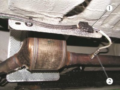
Figure 9-2 - Removing the diagnostic oxygen sensor: 1 - Oxygen sensor diagnostic connector; 2 - diagnostic oxygen sensor
Disconnect the oxygen sensor diagnostic connector from the mounting bracket. Unscrew the diagnostic oxygen sensor 2 (ring spanner 22).
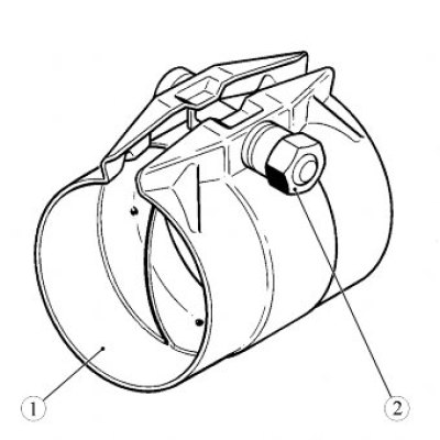
Figure 9-3 - Exhaust system pipe coupling: 1 - coupling sleeve; 2 - nut of the tie bolt
If there is a coupling 1, Figure 9-3, unscrew nut 2 of the coupling clamp bolt connecting the exhaust system pipeline, loosen the coupling (replaceable head 13, extension, ratchet wrench).
If the exhaust system is one piece, then on pipeline 1, Figure 9-4, of the exhaust system, mark with a marker the middle B between marks A and B of the cutting zone, as shown in the figure (ruler).
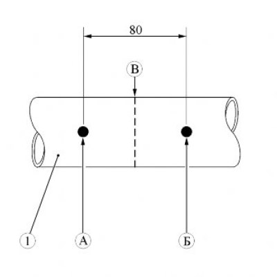
Figure 9-4 - Marking the cutting area of the exhaust system pipeline: 1 - exhaust system pipeline; A, B - cutting zone marks; B - the middle between marks A and B (location of pipeline cutting)
Cut pipe 1, Figure 9-5, of the exhaust system using pipe cutter 2 in accordance with the marking in the middle between the two marks on the pipe (chain pipe cutter type 60 11 00 01 from "Stahl wille").
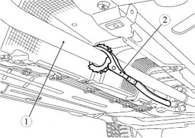
Figure 9-5 - Cutting the exhaust system pipe: 1 - exhaust system; 2 - pipe cutter
Unscrew the two bolts securing the catalytic converter to the exhaust manifold, remove the springs (replacement head 13, extension and ratchet).
Remove catalytic converter 1, Figure 9-1, and sealing ring. The sealing ring must be replaced.
Remove burrs from exhaust pipe parts that will be reused on the vehicle (flat file).
Remove the coupling (if available) from the pipeline (flat head screwdriver). The coupling must be replaced.
Removal the additional muffler
Raise the vehicle to a height convenient for performing the work, unscrew nuts 2, Figure 9-3, of the coupling clamp bolts 1 connecting the exhaust system pipeline, loosen the couplings (13 mm socket head, extension and ratchet, flat screwdriver).
If the exhaust system is one piece, then mark the middle B between the A and B marks of the cutting zones on the exhaust system pipeline with a marker, as shown in Figure 9-4 (ruler).
Cut the exhaust pipe using a pipe cutter between the catalytic converter and the additional muffler in accordance with the marking in the middle between the two marks 1, Figure 9-6 (chain pipe cutter type 60 11 00 01 from "Stahlwille").
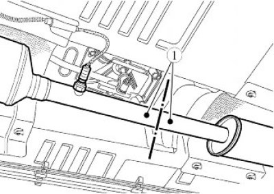
Figure 9-7 - Cutting the exhaust pipe between the catalytic converter and the additional muffler: 1 - cutting zone marks
Cut the exhaust pipe using a pipe cutter between the additional and main mufflers in accordance with the marking in the middle between the two marks 1, Figure 9-7 (chain pipe cutter type 60 11 00 01 from "Stahlwille").
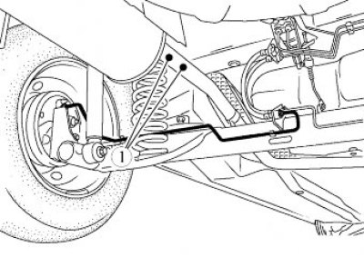
Figure 9-7 - Cutting the exhaust pipe between the main and additional mufflers: 1 - cutting zone marks
Secure the main muffler to the car body with a technological hook (technological hook).
Disconnect the additional muffler bracket from the suspension cushion (if necessary, cut the suspension cushion), remove the additional muffler and couplings (if available). The couplings are subject to replacement (flat screwdriver, technological knife). The operation must be performed with an assistant.
Remove burrs from exhaust pipe parts that will be reused on the vehicle (flat file).
Removal the main muffler
Raise the vehicle to a height convenient for performing the work, unscrew nut 2, Figure 9-3, of the coupling clamp bolt 1, connecting the exhaust system pipeline, loosen the coupling (if available) (13 mm socket head, extension and ratchet, flat screwdriver).
If the exhaust system is one piece, then mark the middle B between marks A and B of the cutting zone on the exhaust system pipeline with a marker, as shown in Figure 9-4 (ruler).
Cut the exhaust pipe using a pipe cutter in accordance with the marking in the middle between the two marks 1, Figure 9-7, on the pipe (chain pipe cutter type 60 11 00 01 from "Stahlwille").
Disconnect the main muffler bracket from the suspension cushion (if necessary, cut the suspension cushion), remove the main muffler and coupling (if available). The coupling needs to be replaced (flat screwdriver, technological knife).
Remove burrs from exhaust pipe parts that will be reused on the vehicle (flat file).
Removal the exhaust system assembly
Disconnect the wiring harness connector from connector 1, Figure 9-2, of the diagnostic oxygen sensor.
Disconnect the oxygen sensor diagnostic connector from the mounting bracket.
Unscrew the diagnostic oxygen sensor 2 (ring spanner 22).
Unscrew the two bolts securing the catalytic converter to the exhaust manifold, remove the springs (replacement head 13, extension and ratchet).
Place the support part of the hydraulic transmission strut (SG-1 "GARO" type hydraulic transmission strut) under the cross beam of levers 1, Figure 9-8, of the rear suspension until it stops.
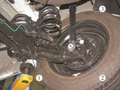
Figure 9-8 - Removing the shock absorbers from the rear suspension arms: 1 - rear suspension arms; 2 - bolt; 3 - rear suspension shock absorber
Loosen and remove bolts 2 securing shock absorbers 3 to the rear suspension arms and carefully lower the rear suspension arms, avoiding tension on the brake hoses (SG-1 "GARO" type hydraulic transmission strut, 21 replaceable head, ratchet wrench).
Remove the exhaust system brackets from the suspension mounts (if necessary, cut the suspension cushions), remove the exhaust system assembly and sealing ring The sealing ring must be replaced (flat screwdriver, technological knife). The operation must be performed with an assistant.
Remove the exhaust system suspension cushions from the body brackets. Cushions that have cracks and tears are subject to replacement (flat head screwdriver).
Installation
Installation of the exhaust system assembly
Lubricate the exhaust system suspension cushions with a soap solution and install them on the body brackets (brush, soap solution, technological container).
Install the new O-ring and exhaust system assembly onto the vehicle, inserting the brackets into the suspension mounts mounted on the body. The operation must be performed by two people.
Install two springs and screw in two bolts securing the catalytic converter to the exhaust manifold. Tightening torque of nuts 21 Nm (2.1 kgf·m) (replaceable head 13, extension and ratchet, torque wrench).
Raise the hydraulic strut with levers 1, Fig. 9-8, of the rear suspension, attach the shock absorbers 3 to the rear suspension levers, install new bolts 2. The tightening torque of the shock absorber mounting bolts is 105 N·m (10.5 kgf·m) (SG-1 "GARO" type hydraulic transmission strut, 21 replaceable head, ratchet handle, torque wrench).
Lower the hydraulic transmission strut support and remove the strut from under the vehicle.
Install the diagnostic 2, Figure 9-2, oxygen sensor in accordance with this TI.
Connect the ground wire terminal to the battery in accordance with the requirements of TI 3100.25100.20597.
Installing the main muffler
Install a new coupling 1, Figure 9-3, onto the exhaust pipe of the additional muffler.
Apply soapy water to the main muffler bracket (brush, soap solution, technological container).
Install the main muffler on the car, inserting the bracket into the suspension cushion on the car body (flat head screwdriver).
Adjust the outlet pipe until it touches the protrusions inside the repair coupling and tighten nut 2 of the coupling 1 tightening bolt connecting the pipe. Tightening torque of the tie bolt nuts 25 Nm (2.5 kgf·m) (replaceable head 13, extension and ratchet, torque wrench).
Installing an additional muffler
Install two new couplings 1, Figure 9-3, on the additional muffler pipes.
Apply soapy water to the additional muffler bracket (brush, soap solution, technological container).
Install an additional muffler on the car, inserting the bracket into the suspension cushion on the car body (flat head screwdriver).
Adjust the outlet pipe until it touches the protrusions inside the repair coupling and tighten the nuts 2 of the coupling tie bolts 1 connecting the pipes. Tightening torque of the tie bolt nuts 25 Nm (2.5 kgf·m) (replaceable head 13, extension and ratchet wrench, torque wrench).
Installation of a catalytic converter
Install catalytic converter 1, Figures 9-1, and a new sealing ring on the vehicle.
Install two springs and screw in two bolts securing the catalytic converter to the exhaust manifold. Tightening torque of bolts 21 Nm (2.1 kgf·m) (replaceable head 13, extension and ratchet, torque wrench).
Install the new coupling 1, Figure 9-3, onto the catalytic converter pipe.
Install the inlet pipe of the additional muffler into the coupling on the outlet pipe of the catalytic converter, adjust the outlet pipe until it touches the protrusions inside the repair coupling and tighten nut 2 of the coupling 1 clamp bolt connecting the pipes. Tightening torque of the tie bolt nut 25 N·m (2.5 kgf·m) (replaceable head 13, extension and ratchet wrench, torque wrench).
Install the diagnostic 2, Figure 12-2, oxygen sensor in accordance with this TI.
Connect the ground wire terminal to the battery in accordance with the requirements of TI 3100.25100.20597.
Present the vehicle to the Quality Control Department. The Quality Control Department will check the vehicle for compliance with the requirements of TU 017200-254-00232934, paragraphs 1.19.14.2, 2.19.21.3 in the scope of work performed.
18.05.2026 09:49