
Device Features
Exhaust gases are discharged from the engine through the exhaust manifold and the exhaust system, which includes a catalytic converter 1, figures 12-1 and 12-2, an additional muffler 2 and a main muffler 3. The gas exhaust system is made in the form of a single welded structure, which is suspended from the car body using rubber cushions. It is possible to replace individual components of the gas exhaust system using pipeline cutting and further assembly using repair clamping couplings. For this purpose, two zones A and B are provided on the exhaust system for cutting. On the catalytic converter side, the exhaust system is flange-mounted to the exhaust manifold using stud bolts and nuts.
General view of the exhaust system from the bottom of a car with a 1.6 liter engine
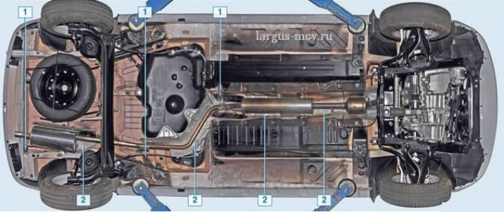
1 – a rubber pillow of a suspension bracket of system of release; 2 - heat shield
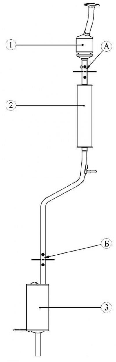
Figure 12-1 - The exhaust system of a car with a K4M engine: 1 - catalytic converter; 2 - additional muffler; 3 - main muffler; A - cutting zone; B - cutting zone
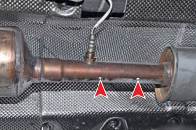
The location of the marks on the pipe between the converter and the additional muffler
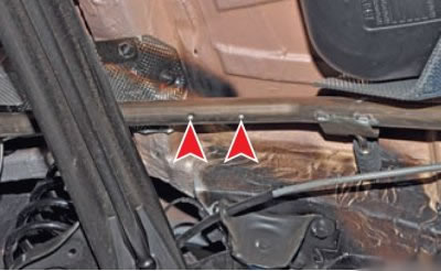
The location of the marks on the pipe between the additional and main mufflers
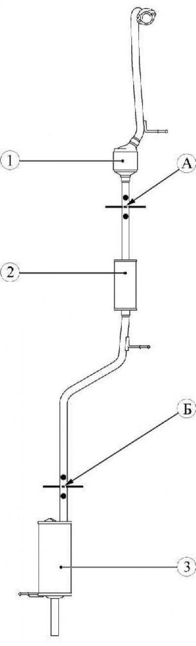
Figure 12-2 - The exhaust system of a car with a K7M engine: 1 - catalytic converter; 2 - additional muffler; 3 - main muffler; A - cutting zone; B - cutting zone
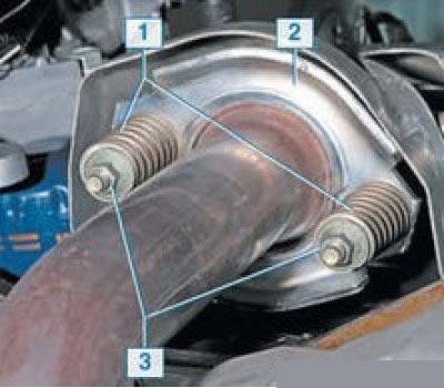
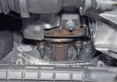
Connection of a reception pipe with a final collector of the engine 1,6 (8V): 1 - spring; 2 - pressure plate; 3 - nut
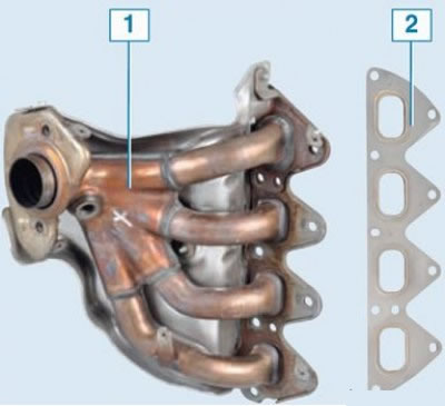
Engine exhaust manifold 1.6 (16V): 1 - exhaust manifold; 2 - manifold gasket
The exhaust manifold is used to collect exhaust gases from all engine cylinders into one exhaust channel.
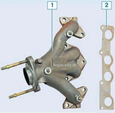
Engine exhaust manifold 1.6 (8V): 1 - exhaust manifold; 2 - manifold gasket
Connection of a reception pipe with a final collector of the engine 1,6 (16V)
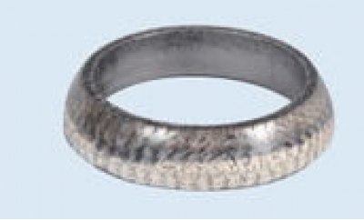
O-ring with spherical surface
Removing the exhaust system from the car
Put the car on a two-post lift, apply the parking brake, turn off the ignition and disconnect the wire terminal "masses" from the battery.
For vehicles with K7M engine
Remove the engine crankcase protection.
Remove block 1, Figure 12-3, of the control oxygen sensor from the holder by sliding it.
Disconnect the wiring harness connector from the oxygen control sensor connector.
Disconnect clamp 2.
Unscrew the control oxygen sensor 3 (tool Mot. 1495 or interchangeable insert 22 from the set of type 811382 f. "USAG").
Operations for all vehicle configurations
Disconnect the harness connector from connector 1, Figure 12-4, diagnostic oxygen sensor.
Disconnect the diagnostic oxygen sensor block from the mounting bracket.
Unscrew diagnostic oxygen sensor 2 (tool Mot. 1495 or interchangeable insert 22 from the set of type 811382 f. "USAG").
Unscrew the two nuts 1, Figure 12-8, of the studs securing the catalytic converter to the exhaust manifold 3, remove the springs 2 (interchangeable head 10, extension and ratchet).
For vehicles without ABS
Disconnect the rear brake adjuster rod from the rear suspension arms (flathead screwdriver, pliers).
Operations for all vehicle configurations
Bring under the transverse beam of the levers 1, Figure 12-11, the rear suspension to the stop the supporting part of the hydraulic transmission rack (hydraulic transmission rack type SG-1 "GARO").
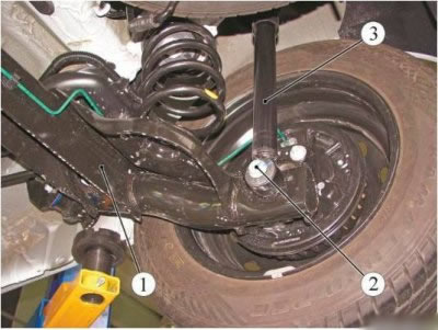
Figure 12-11 - Detaching the shock absorbers from the rear suspension arms: 1 - rear suspension arms; 2 - bolt; 3 - rear suspension shock absorber
Unscrew and remove the bolts 2 fastening the shock absorbers 3 to the rear suspension arms and carefully lower the rear suspension arms avoiding tension on the brake hoses (hydraulic transmission rack type SG-1 "GARO", interchangeable head 19, ratchet knob).
Remove the brackets for the exhaust system from the suspension cushions (cut suspension cushions if necessary), remove the exhaust system assembly and O-ring. The O-ring must be replaced (flat screwdriver, utility knife). Perform the operation with an assistant.
Remove the exhaust system suspension mounts from the body brackets. Cushions that are cracked or torn should be replaced (flat screwdriver).
Installation of system of release of the fulfilled gases in gathering
Lubricate the suspension cushions of the exhaust system with soapy water and install on the body brackets (brush, soap solution, technological containers).
Install the new O-ring and exhaust system assembly to the vehicle by inserting the brackets into the suspension mounts mounted on the body. The operation is performed by two performers.
Install two springs 2, Figure 12-8, and screw on two nuts 1 of the studs securing the catalytic converter to the exhaust manifold 3. The tightening torque of the nuts is 21 Nm (2.1 kgf·m) (interchangeable head 10, extension and ratchet wrench, torque wrench).
Raise the hydraulic strut with arms 1, Figure 12-11, of the rear suspension, attach the shock absorbers 3 to the rear suspension arms, install new bolts 2. Tightening torque of the shock absorber mounting bolts 105 Nm (10.5 kgf·m) (hydraulic transmission rack type SG-1 "GARO", interchangeable head 19, ratchet knob, torque wrench).
Lower the support part of the hydraulic transmission strut and remove the strut from under the vehicle.
Install diagnostic 2, Figure 12-4, oxygen sensor.
For vehicles without ABS
Connect the rear brake control rod to the rear suspension arms (flathead screwdriver, pliers).
For vehicles with K7M engine
Install control 3, Figure 12-3, oxygen sensor.
Install the engine undertray.
Operations for all vehicle configurations
Attach wire terminal "masses" to the battery.
Installation of the main muffler
Install a new coupling 1, Figure 12-5, on the exhaust pipe of the additional muffler.
Install the main muffler on the car, while inserting the bracket into the suspension cushion on the car body (flat screwdriver).
Align the exhaust pipeline until it comes into contact with the protrusions inside the repair sleeve and tighten the nut 2 of the coupling bolt 1 connecting the pipeline. Tie bolt nut tightening torque 25 Nm (2.5 kgf·m) (socket head 13, extension and ratchet wrench, torque wrench).
Installing an additional silencer
Install two new couplings 1, Figure 12-5, on the pipes of the additional muffler.
Apply soapy water to the muffler bracket (brush, technological container).
Install an additional muffler on the car, while inserting the bracket into the suspension cushion on the car body (flat screwdriver).
Align the exhaust pipeline until it comes into contact with the protrusions inside the repair sleeve and tighten the nuts 2 of the coupling bolts 1 connecting the pipelines. Tie bolt nut tightening torque 25 Nm (2.5 kgf·m) (socket head 13, extension and ratchet wrench, torque wrench).
Installing a catalytic converter
Install catalytic converter 1, figures 12-1 and 12-2, and a new O-ring to the vehicle.
Install two springs 2, Figure 12-8, and screw on two nuts 1 of the studs securing the catalytic converter to the exhaust manifold 3. The tightening torque of the nuts is 21 Nm (2.1 kgf·m) (interchangeable head 10, extension and ratchet wrench, torque wrench).
For vehicles with K7M engine
Apply soapy water to the catalytic converter bracket and install the bracket to the suspension mount on the body (brush, technological container).
Operations for all vehicle configurations
Install a new coupling 1, Figure 12-5, on the catalytic converter pipe.
Install the intake pipe of the additional muffler into the coupling on the exhaust pipe of the catalytic converter, align the exhaust pipeline until it comes into contact with the protrusions inside the repair coupling and tighten the nut 2 of the coupling bolt 1 connecting the pipelines. Tie bolt nut tightening torque 25 Nm (2.5 kgf·m) (socket head 13, extension and ratchet wrench, torque wrench).
For vehicles with K7M engine
Install control 3, Figure 12-3, oxygen sensor.
Install the engine undertray.
Operations for all vehicle configurations
Install diagnostic 2, Figure 12-4, oxygen sensor.
Attach wire terminal "masses" to the battery.