



Removal
Place the vehicle on a two-post lift, apply the parking brake and turn off the ignition (electro-hydraulic lift type P-3.2G with a lifting capacity of 3.2 t).
Remove the battery in accordance with the requirements of TI 3100.25100.20597.
Remove the battery tray.
Remove the ECM controller in accordance with the requirements of this TI.
Remove the engine crankcase protection in accordance with the requirements of TI 3100.25100.20594.
Install crossbar 1, Figure 14-1, on the gutters of the engine compartment and hook it to the lifting eye on the engine on the flywheel side (crossbar for hanging the engine type RST-500 ES f. "RANGER").
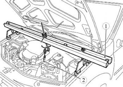
Figure 11-1 - Installing the engine support crossmember:
1 - crossbar for hanging the engine; 2 - lifting eyeMark the position of the left engine mount support on the body with a marker.
Loosen the power steering pipe mounting bolt (if the car is equipped with it) to the left engine mount (replacement head 13, extension, ratchet).
Unscrew nut 1, Fig. 11-2, studs securing the gearbox to cushion 2 of the left engine mount (replacement head 16, extension, ratchet).
If necessary, use a bronze drift to knock out stud 5 of the gearbox mount from the left engine mount cushion (bronze technological punch, hammer).
Unscrew two nuts 4 and remove the left engine mount cushion (replacement head 18, ratchet, extension).
Unscrew the four bolts 1, Fig. 11-3, securing the left engine mount support to the body and remove the left support 2 (replacement head 13, extension, ratchet)
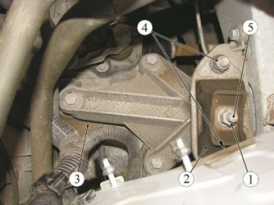
Figure 11-2 - Removing the gearbox from the left engine mount: 1 - gearbox mounting stud nut; 2 - left engine mount cushion; 3 - gearbox; 4 - left engine mount support mounting nut; 5 - gearbox mounting stud
Loosen the three bolts 3 securing the left engine mount bracket to the gearbox and remove the bracket 4 (replacement head 16, extension, ratchet).
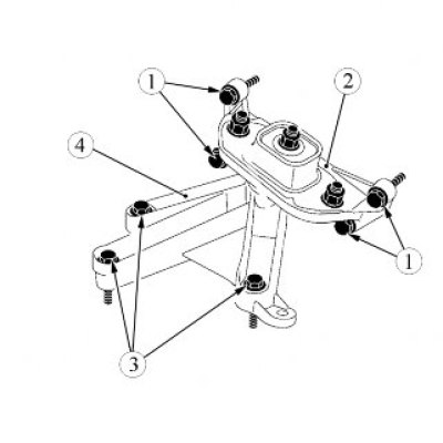
Figure 11-3 - Removing the left engine mount: 1 - bolt securing the left engine mount support to the body; 2 - left engine mount support; 3 - bolt for fastening the bracket of the left engine mount to the gearbox; 4 - left engine mount bracket
Installation
Install bracket 4, Figure 11-3, of the left engine mount support onto the gearbox. Tightening torque of bolts 3 fastenings 62 Nm (6.2 kgf·m) (replacement head 16, extension, ratchet).
Install the left support 2 of the engine mount onto the vehicle body. Tightening torque of bolts 1 securing the left suspension support to the body 21 N·m (2.1 kgf·m) (replaceable head 13, extension, ratchet, torque wrench).
Install cushion 2, Figure 14-2, of the left engine mount support onto the support, install and tighten new nuts 4 of the suspension cushion mounting studs. Tightening torque of the nuts securing the studs of the left engine mount cushion 105 N·m (10.5 kgf·m) (replaceable head 18, extension, ratchet, torque wrench)
Install nut 1 of the gearbox mounting stud to cushion 2 of the left engine mount. Tightening torque of the left support mounting stud nut 62 N·m (6.2 kgf·m) (replaceable head 16, extension, ratchet, torque wrench).
Install and tighten the power steering line mounting bolt (if the car is equipped with it) to the left engine mount. Tightening torque of the power steering pipeline mounting bolt 21 N·m (2.1 kgf·m) (replaceable head 13, extension, ratchet, torque wrench).
Disconnect the crossbar hook from the lifting eye 2, Figure 11-1, on the engine flywheel side and remove crossbar 1.
Install engine crankcase protection in accordance with the requirements of TI 3100.25100.20546.
Install the ECM controller in accordance with the requirements of this TI.
Install the battery tray.
Install the battery in accordance with the requirements of TI 3100.25100.20597.
Present the vehicle to the Quality Control Department. The Quality Control Department will check the vehicle for compliance with the requirements of TU 017200-254-00232934, clause 1.19.6, in the scope of work performed.
[Original publication on the website: ladaman.ru]