



Removal
For all vehicle trim levels
Place the vehicle on a two-post lift, apply the parking brake, turn off the ignition and disconnect the battery ground terminal (electro-hydraulic lift type P-3.2G with lifting capacity of 3.2 t, spanner 10).
Remove the right front wheel in accordance with the requirements of TI 3100.25100.20594.
Raise the vehicle to a height convenient for performing the work.
Remove the right inner wheel arch trim in accordance with the requirements of TI 3100.25100.20599.
Remove the drive belt of the attachment units in accordance with the requirements of Section 4 of this technological instruction.
Remove the engine mudguard in accordance with the requirements of TI 3100.25100.20594.
Remove the starter in accordance with the requirements of TI 3100.25100.20597, without disconnecting the terminal and connector of the wiring harnesses suitable for the starter, and hang it on a technological hook (technological hook).
Block the engine flywheel through the starter mounting hole (flat head screwdriver).
For cars with H4M engine
Loosen bolt 1, Figure 6-1, of the fastening and remove the crankshaft damper (replaceable head 19, ratchet).
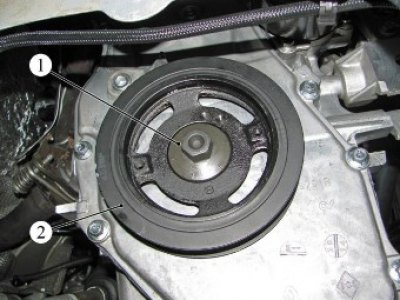
Figure 6-1 - Removing the H4M engine crankshaft damper: 1 - damper mounting bolt; 2 - crankshaft damper
For cars with engines 21129 and 21179
Unscrew bolt 1, Figure 6-2, securing the damper, remove washer 2 and damper 3 from the crankshaft (replacement head 17, ratchet).
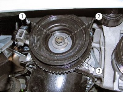
Figure 6-2 - Crankshaft Damper: 1 - damper mounting bolt; 2 - washer; 3 - crankshaft damper
Installation
For cars with K4M engine
Install damper 2, Figure 6-1, on the crankshaft and secure with bolt 1. Tightening torque of the damper mounting bolt is 90-110 N·m (9.0-11.0 kgf·m) (replaceable head 19, ratchet, torque wrench).
For cars with engines 21129 and 21179
Install the damper on the crankshaft and secure with bolt 1, Figure 6-2, with washer 2. The tightening torque of the damper mounting bolt is 90-110 N·m (9.0-11.0 kgf·m) (replaceable head 17, ratchet, torque wrench).
Operations are common for all vehicle configurations
Install the starter in accordance with the requirements of TI 3100.25100.20597.
Install the drive belt of the attachment units in accordance with the requirements of Section 4 of this technological instruction.
Install the right inner wheel arch lining in accordance with the requirements of TI 3100.25100.20599.
Install the right front wheel in accordance with the requirements of TI 3100.25100.20594.
Connect the ground wire terminal to the battery in accordance with the requirements of TI 3100.25100.20597.
Present the vehicle to the Quality Control Department. The Quality Control Department will check the vehicle for compliance with the requirements of TU 017200-254-00232934, paragraphs 1.19.5, 1.19.6, 1.19.14.