



Note: For replacement part numbers, see here, or here (the crankshaft pulley may differ depending on the engine and the presence of air conditioning)
Removal
Operations are common for all vehicle configurations
Place the vehicle on a two-post lift, apply the parking brake, turn off the ignition and disconnect the ground wire from the battery.
For cars with K4M engine
Remove the inlet manifold.
Remove the intake silencer. (see here)
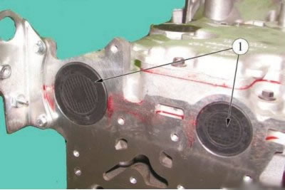
Figure 4-1 - Removing the camshaft plugs: 1 - camshaft plug
Pierce the center of the plugs 1, Figure 4-1, of the camshafts with a screwdriver and remove the plugs (flat screwdriver, technological hook).
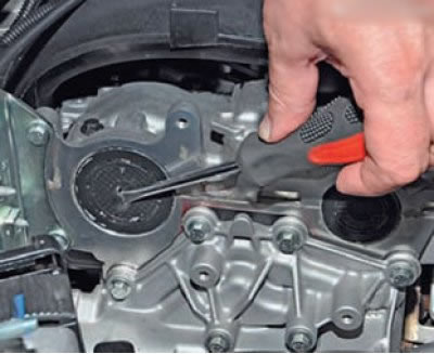 |
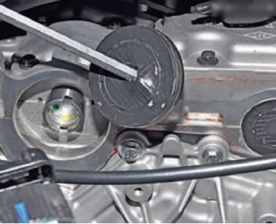 |
To check the position and fixation of TDC, on the front wall of the cylinder block (under the starter) there is a threaded hole into which a plug bolt 1 is screwed, Figure 4-2.
Remove the plug bolt for the TDC locking pin hole (torx E14 socket head, extension, ratchet wrench).
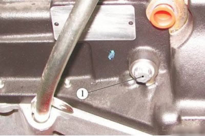
Figure 4-2 - Removing the TDC locking plug: 1 - TDC locking bolt hole plug
Remove the engine crankcase guard (see here).
Remove the right front wheel.
Remove the right side mudguard (see here).
Remove the accessory drive belt (see here).
Position the camshaft grooves 1, Figure 4-3, almost horizontally and offset downwards from the shaft axes in the direction of normal rotation (clockwise when viewed from the timing drive side) (replacement head 16, extension, ratchet wrench).

Figure 4-3 - Installing the TDC lock: 1 - camshafts; 2 - TDC lock
Install the TDC locking device (tDC locking device Mot. 1489 or 67.7820-9701 L).
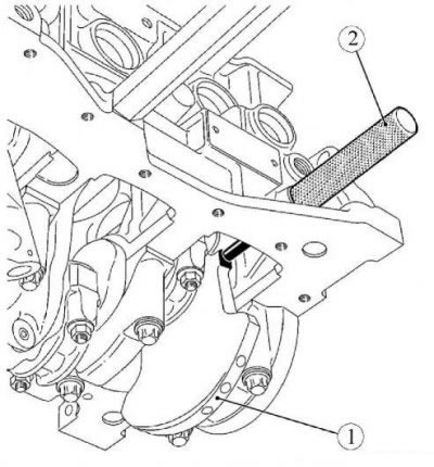
Figure 4-4 - Setting the crankshaft to TDC: 1 - crankshaft; 2 - TDC lock
Note: If there is no special lock, you can use an M10 bolt. The length of the threaded part is 75 mm.
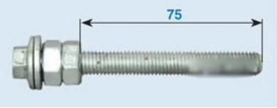
If the bolt is longer, then screw on two adjusting nuts and lock them so that the length of the threaded part of the bolt is 75 mm.
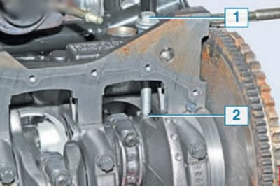
Assembled device (mounting pin) screw it into the threaded hole of the cylinder block. When the crankshaft is in the TDC position of pistons of the 1st and 4th cylinders, the installation pin 1 should screw into the hole to the end of the thread and rest against the milled area 2 on the crankshaft and block the shaft when trying to turn it clockwise (shown with the oil pan removed). The same thing, from a different angle, is shown in Figure 4-4).
Turn crankshaft 1, Figure 4-4, clockwise until it rests against the TDC locking pin (replacement head 18, extension, ratchet wrench).
The grooves of the camshafts 1, Figure 4-5, must be in a horizontal position with a downward offset from the shaft axes.
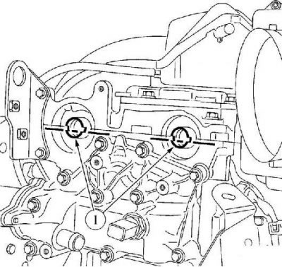
Figure 4-5 - Position of camshaft grooves at TDC: 1 - camshafts
Unscrew the TDC lock.
Lock the flywheel with a screwdriver (flat head screwdriver).
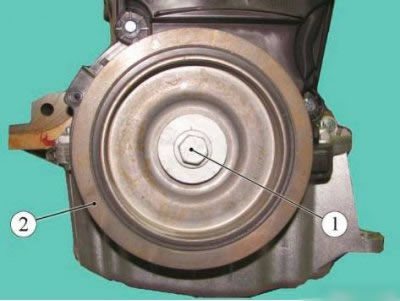
Figure 4-6 - Removing the crankshaft pulley of the K4M engine: 1 - camshafts; 2 - crankshaft pulley
Loosen bolt 1, Figure 4-6, fastening (replacement head 18, extension, ratchet wrench)
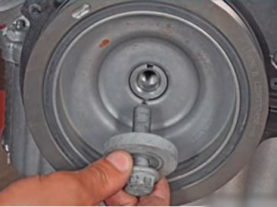
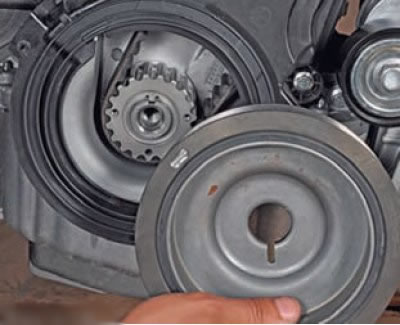
... and remove the crankshaft pulley
For cars with K7M engine
Remove the right front wheel.
Remove the right side mudguard (see here).
Remove the accessory drive belt (see here).
Remove the engine crankcase guard (see here).
Unscrew the plug of the hole for the TDC locking device (torx E14 socket head, extension, ratchet wrench).
Install the TDC locking device (tDC locking device Mot. 1489 or 67.7820-9701 L).
Set the piston of the 1st cylinder to TDC and lock the crankshaft with a lock.
Lock the flywheel with a screwdriver (flat head screwdriver).
Loosen bolt 1, Figure 4-7, of the fastening and remove pulley 2 of the crankshaft (replacement head 18, extension, ratchet wrench).
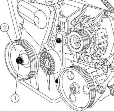
Figure 4-7 - Removing the crankshaft pulley of the K7M engine: 1 - camshafts; 2 - crankshaft pulley
Installation
For cars with K4M engine
Attention. The bolt securing the crankshaft pulley must be replaced.
Caution: Before installing the crankshaft pulley, degrease the bearing surface of the pulley and the nose of the crankshaft.
Install tool 1, Figure 4-8, to secure the camshafts (mot. 1496 fixture).
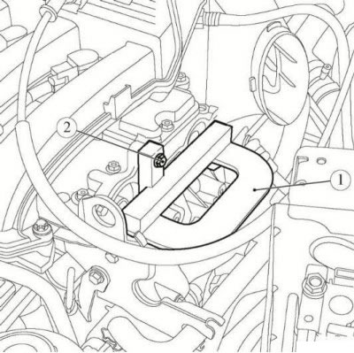
Figure 4-8 - Installing the valve timing tool: 1 - Timing adjustment tools Mot. 1496; 2 - bolt
Secure the device to the ends of the camshafts with bolt 2 (replacement head 10, extension, ratchet).
Note: If you do not have a special device for fixing camshafts, you can make a simple retainer yourself using the drawing below:
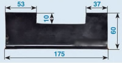
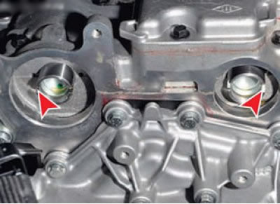
Turn the crankshaft clockwise until the grooves on the camshafts are almost horizontal (parallel to the plane of the joint between the cylinder head and cover) and will be shifted downwards relative to the axes of the camshafts.
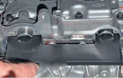
... and install the retainer
Make sure that the crankshaft is securely locked with the TDC lock; if necessary, turn the crankshaft further by turning the flywheel with a screwdriver (locking pin Mot. 1489 or 67.7820-9701 L, flat-head screwdriver).
The crankshaft groove must face upward.
Install pulley 2, Figure 4-6, on the crankshaft and secure with a new bolt 1 (replacement head 18, extension, ratchet wrench).
Tighten the crankshaft pulley mounting bolt to 40 Nm (4.0 kgf·m) and further tighten by 145° ±15° (replaceable head 18, extension, torque wrench).
Unscrew the TDC lock.
Apply sealant to the thread of the plug bolt 1, Figure 4-2, the hole for the TDC lock and tighten. Tightening torque of the plug 20 Nm (2.0 kgf·m) (torx E14 socket head, extension, ratchet wrench, torque wrench).
Remove tool 1, Figure 4-7, for fixing the camshafts (replacement head 10, extension, ratchet).
Install new camshaft plugs, pressing them in with light blows.
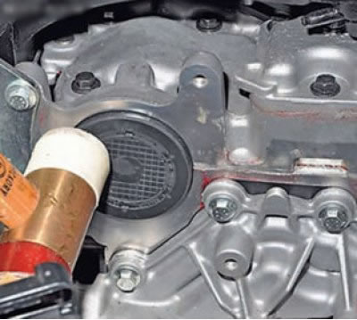
Install the accessory drive belt.
Install the engine crankcase guard.
Install the right side mudguard.
Install the right front wheel.
Install the intake noise muffler.
Install the inlet manifold.
For cars with K7M engine
Attention. The crankshaft pulley mounting bolt must be replaced.
Caution: Before installing the crankshaft pulley, degrease the bearing surface of the pulley and the nose of the crankshaft.
Make sure that the crankshaft is securely locked with the TDC lock; if necessary, turn the crankshaft further by turning the flywheel with a screwdriver (locking pin Mot. 1489 or 67.7820-9701 L, flat-head screwdriver).
Install pulley 2, Figure 4-7, on the crankshaft and secure with a new bolt 1 (replacement head 18, extension, ratchet wrench).
Tighten the crankshaft pulley mounting bolt to 30 Nm (3.0 kgf·m) and further tighten by 100° ±5° (replaceable head 18, extension, torque wrench).
Unscrew the TDC lock.
Apply sealant to the threads of the TDC locking plug and tighten the plug. Tightening torque of the plug 20 Nm (2.0 kgf·m) (torx E14 socket head, extension, ratchet wrench, torque wrench).
Install the engine crankcase guard.
Install the accessory drive belt.
Install the right side mudguard.
Install the right front wheel.
Operations are common for all vehicle configurations
Connect the ground wire terminal to the battery.