
Removing
Place the vehicle on a two-post lift, apply the parking brake and turn off the ignition.
For vehicles with air conditioning
Completely pump out the refrigerant from the air conditioning system.
For vehicles with a body "station wagon"
Tilt the rear row of seats forward (for 5-seater configuration) or middle row (for 7-seater configuration).
Detach and lift upholstery.
Remove the hatch cover of the electric fuel pump.
Disconnect connector 1, Figure 2-1, rear wiring harness from fuel pump module 2.
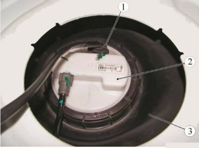
Figure 2-1 - Disconnecting the rear wiring harness block from the fuel pump module: 1 - block of the rear wiring harness to the fuel pump module; 2 - electric fuel pump module; 3 - fuel tank
Start the engine and let it run at idle until it comes to a complete stop to relieve pressure in the fuel system, ensuring that exhaust gases are removed (exhaust coil with fan type SERF/SP f. "SovPlym"). Switch off the ignition.
Disconnect wire terminal "masses" from the battery.
Connect the block, wiring harness to the fuel pump module.
Install the hatch cover of the electric fuel pump.
Install and secure the floor upholstery.
lower rear (for 5-seater configuration) or medium (for 7-seater configuration) row of seats.
Remove pipe 1, Figure 2-2, air intake.
For vehicles with K7M engine:
- Remove air filter housing 3.
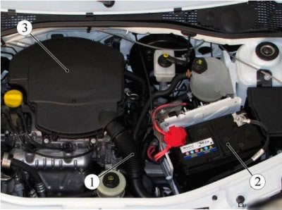
Figure 2-2 - Removing the air filter housing and battery on a car with a K7M engine: 1 - air intake pipe; 2 - battery; 3 - air filter housing
For vehicles with K4M engine:
- - remove muffler 1, Figure 2-3, intake noise;
- - remove protection 2 of the fuel rail;
- - remove block 3 throttle valve.
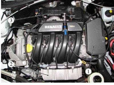
Figure 2-3 - Removing the elements of the intake system of a car with a K4M engine: 1 - intake silencer; 2 - fuel rail protection; 3 - throttle valve block
Operations common to all vehicle configurations
Remove the battery. Remove the battery tray.
Remove controller 1, Figure 2-4, ECM.
Remove the fuses and the engine wiring harness relay from the holders in the mounting block 2.
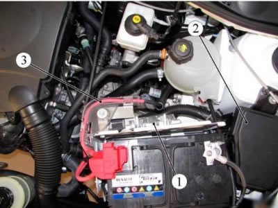
Figure 2-4 - Removing the ECM and Disconnecting the Engine Harness: 1 - ECM controller; 2 - mounting block; 3 - engine wiring harness
Remove the 3 wire harness from the engine from the holder on the shelf under the battery.
Lay the wiring harness with fuses and relays on the engine.
Remove front wheels.
Loosen the hub nuts using the tool (Rou device. 604-01, interchangeable head 32, knob).
Remove the engine crankcase protection.
For vehicles with K4M engine additionally:
- - remove the front bumper;
- - Disconnect the hose of the gasoline vapor recovery system.
Operations common to all vehicle configurations
Remove the inner lining and side mudguards.
Unscrew the plug 1, Figure 2-5, of the drain hole in the gearbox housing 2 and drain the oil (key for an internal square 8 mm, technological capacity).
Drain coolant.
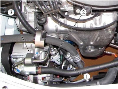
Figure 2-5 - Draining the gearbox oil and disconnecting the wiring harness from the electric fan: 1 - plug of the drain hole of the gearbox; 2 - gearbox; 3 - wiring harness to the electric fan of the engine cooling system; 4 - electric fan of the engine cooling system
Disconnect block (two pads - for vehicles with air conditioning system) harness 3 of wires from the electric fan 4 of the engine cooling system.
Disconnect the wiring harness from the engine cooling fan.
For vehicles with power steering additionally:
Disconnect the connector 1, Figure 2-6, of the wiring harness from the power steering pressure sensor 2.
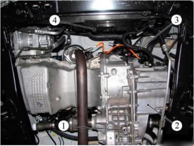
Figure 2-6 - Disconnecting the harness connector from the power steering system pressure sensor: 1 - block of the wiring harness to the pressure sensor; 2 - pressure sensor; 3 - power steering pump
Loosen the bolts and nuts securing the power steering pipes:
- - on top of subframe 2, figure 2-7, front suspension (interchangeable head 10, ratchet wrench);
- - on bracket 3, Figure 2-8, fastenings of attachments (for a car with a K7M engine) (interchangeable head 10, ratchet wrench);
- on cylinder block 3, Figure 2-9 (interchangeable head 13, ratchet wrench).
Figure 2-7 - Disconnecting the power steering pipe from the front suspension subframe: 1 - power steering pipeline; 2 - front suspension subframe; 3 - a bolt of fastening of the pipeline of the hydraulic booster of a steering
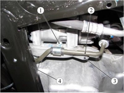
Figure 2-8 - Disconnecting the power steering pipe from the attachment mounting bracket (for a car with a K7M engine): 1 - a bolt of fastening of the pipeline of the hydraulic booster of a steering; 2 - power steering pipeline; 3 - mounting bracket for mounted units; 4 - front suspension subframe
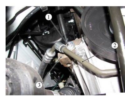
Figure 2-9 - Disconnecting the power steering pipe from the cylinder block: 1 - nut for fastening the power steering pipeline; 2 - power steering pipeline; 3 - cylinder block
Unscrew the tank cap 1, Figure 2-10, of the power steering pump and pump out the working fluid from the system (hand pump, process tank).
Release clamp 6, disconnect hose 4 from power steering pump 5 and install plugs in the openings of the pipeline and pump (clamp pliers Mot. 1202-02, technological plugs).
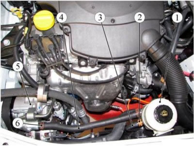
Figure 2-10 - Disconnecting the pipeline from the power steering pump: 1 - power steering reservoir; 2 - clamp; 3 - hose; 4 - hose; 5 - power steering pump; 6 - collar
Release clamp 2, disconnect hose 2 from the reservoir of the power steering pump and install plugs in the openings of the hose and reservoir (clamp pliers Mot. 1202-02, technological plugs).
Remove the power steering pump reservoir with hose 4 as an assembly.
Remove hose 3 from the holder on the electric fan housing of the engine cooling system.
Unscrew the bolt 1, Figure 2-11, fastening the bracket 2, unscrew the nut 3 of the fitting, disconnect the high pressure pipeline 4 from the power steering pump 5 and install plugs in the openings of the pipeline and the power steering pump (for a car with a K7M engine) (wrenches 10, 17).
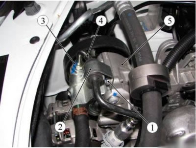
Figure 2-11 - Disconnecting the high pressure pipeline from the power steering pump for a car with a K7M engine: 1 - bolt; 2 - mounting bracket; 3 - fitting nut; 4 - high pressure pipeline of the power steering; 5 - power steering pump
For vehicles with K4M engine additionally:
- unscrew the bolts securing the high pressure pipe on the gearbox and gearbox support (interchangeable head 13, ratchet wrench).
For vehicles with an air conditioning system additionally: - disconnect block 1, Figure 2-12, wiring harness from refrigerant pressure sensor 2;
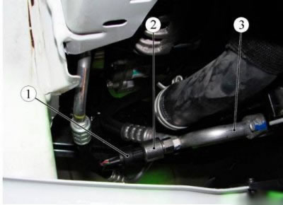
Figure 2-12 - Disconnecting the harness connector from the refrigerant pressure sensor: 1 - block of the wiring harness of the refrigerant pressure sensor; 2 - refrigerant pressure sensor; 3 - pipeline of the air conditioning system
- unscrew the bolt securing the pipeline to the air conditioning compressor, disconnect the pipeline from the compressor and install plugs in the openings of the pipeline and the compressor (wrench 10, technological plugs).
Operations common to all vehicle configurations
Disconnect the ball end 1, Figure 2-13, of the accelerator cable from the throttle pipe.
Press lock 2 and remove accelerator cable 4 from bracket 3. Disconnect:
- block of the wiring harness from the canister purge solenoid valve;
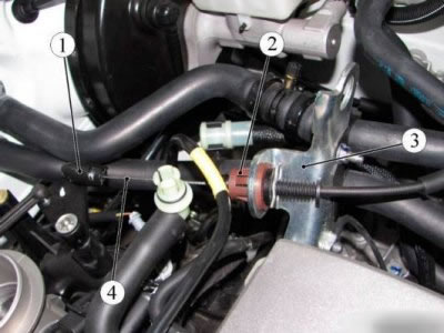
Figure 2-13 - Disconnecting the accelerator cable: 1 - ball tip of the accelerator drive cable; 2 - latch; 3 - bracket; 4 - accelerator cable
- brake booster vacuum hose from the intake manifold;
- - crankcase ventilation hose from the intake manifold;
- - fuel pipe 1, Figure 2-14, from fuel rail 2.
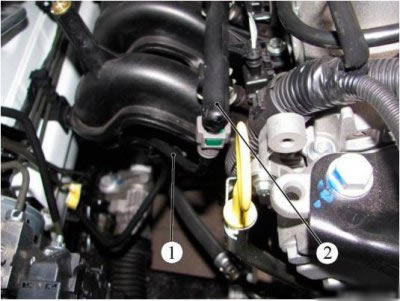
Figure 2-14 - Disconnecting the fuel pipe from the fuel rail: 1 - fuel pipe; 2 - fuel rail
Attention. For van vehicles, preliminarily cover the place of the fuel pipe connector with the fuel rail with a rag and prevent fuel from escaping when the fuel line is disconnected, since the pressure in the fuel line is maintained.
Release clamps 1, Figure 2-15, and disconnect hoses 2 of the cooling system from the engine (clamp pliers Mot. 1202-02).
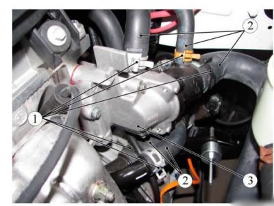
Figure 2-15 - Disconnecting the cooling system hoses: 1 - clamp; 2 - hose of the cooling system; 3 - thermostat
Remove the hoses 1, Figure 2-16, of the cooling system from the holders 2.
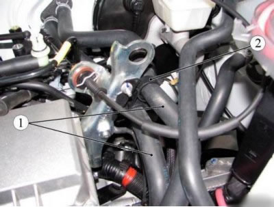
Figure 2-16 - Disconnecting the cooling system hoses: 1 - hose of the cooling system; 2 - holder
Unscrew bolts 1, figure 2-17, fixings and disconnect wires 2 "masses" from gearbox 3 (interchangeable head 13, extension, ratchet wrench).
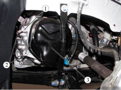
Figure 2-17 - Disconnecting wires "masses" from gearbox: 1 - fastening bolt; 2 - wire "masses"; 3 - gearbox
Remove the front brakes 1, Figure 2-18.
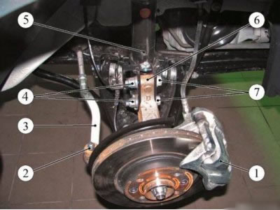
Figure 2-18 - Disconnecting the front suspension elements: 1 - front brake; 2 - a nut of fastening of a finger of a spherical support; 3 - outer tie rod end; 4 - a nut of a bolt of fastening of a shock-absorber rack; 5 - shock absorber; 6 - rotary fist; 7 - a bolt of fastening of a shock-absorber rack
Unscrew the nuts 2 fastening the pins of the ball joints of the outer tips 3 of the steering rods and press the pins out of the steering knuckle levers 6 (interchangeable head 16, knob, Tav. 476).
Unscrew the nuts 4 of the bolts securing the shock absorber struts 5 to the steering knuckles, remove the bolts 7 and disconnect the shock absorber struts from the steering knuckles (wrench 18, interchangeable head 18, knob).
Remove front wheel drives.
Unscrew and remove the bolts 1, Figure 2-19, of the upper fastening of the braces 2 of the front suspension subframe to the body (interchangeable head 13, ratchet wrench).
For vehicles with K4M engine additionally:
- unscrew the bolts securing the heat shield of the steering mechanism and remove the heat shield (interchangeable head 13, ratchet wrench).
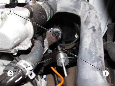
Figure 2-19 - Disconnecting the front suspension elements: 1 - a bolt of the top fastening of an extension of a subframe of a forward suspension bracket; 2 - stretching the front suspension subframe; 3 - front suspension subframe
Operations common to all vehicle configurations
Unscrew the two bolts securing the steering gear to the front suspension subframe (interchangeable head 18, ratchet knob).
Attach the steering gear to the body (technological hooks).
For vehicles with JH3 gearbox
Disconnect:
- - cable 1, Figure 2-20, clutch drive from fork 2 to release the clutch;
- - the clutch cable from the clutch cable sheath stopper.
Remove the protective cover 1, Figure 2-21, of the gear lever on the gearbox.
Unscrew the bolt 2 fastening the linkage of the gearbox control drive (interchangeable head 10, ratchet wrench).
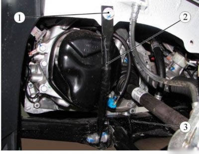
Figure 2-20 - Disconnecting the clutch cable from the gearbox: 1 - clutch cable; 2 - clutch release fork; 3 - clutch cable sheath stopper
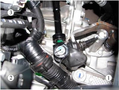
Figure 2-21 - Disconnecting the transmission control drive linkage: 1 - protective cover for the gear lever; 2 - a bolt of fastening of draft of a drive of management of a transmission; 3 - thrust of the gearbox control drive
Fix the link 3 of the gearbox control drive on the body (technological hook).
For vehicles with JR5 gearbox
Disconnect the hinges 1, Figure 2-22, of the selector and shift cables from the gearbox levers 2 (flat screwdriver);
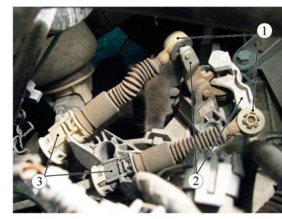
Figure 2-22 - Disconnecting the select and shift cables from the gearbox: 1 - cable hinge; 2 - gear lever; 3 - cable sheath stopper
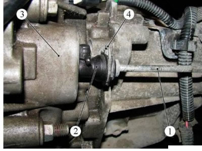
Figure 2-23 - Disconnecting the clutch hydraulic pipeline from the slave cylinder: 1 - clutch hydraulic pipeline; 2 - working cylinder of the hydraulic clutch; 3 - gearbox; 4 - latch
Disconnect the stoppers 3 of the sheaths of the select and shift cables from the bracket on the gearbox by pressing the tabs on both sides.
Disconnect the pipeline 1, Figure 2-23, of the clutch hydraulic drive from the working cylinder 2 by pressing the lock 4.
Attention. Do not pull on the latch. In case of any erroneous action, the pipeline must be replaced.
Drain the brake fluid from the pipeline and plug the openings of the pipeline and the clutch slave cylinder (technological capacity, technological plugs).
Operations common to all vehicle configurations
Remove the rear engine mount.
Disconnect the exhaust system.
Move the exhaust pipe towards the rear of the vehicle and hang it from the body (technological hooks).
Remove the front suspension subframe.
Install the traverse on the gutter grooves of the engine compartment and hook it with two hooks to the lifting eyes on the engine from the timing side and from the flywheel side (traverse for hanging the engine type RST-500 ES f. "RANGER").
Remove the right engine mount.
Unscrew the nut 1, Figure 2-24, the studs of the gearbox to the pillow 2 of the left engine mount (interchangeable head 16, extension, crank).
Lower the engine/transmission assembly to separate it from the left engine mount.
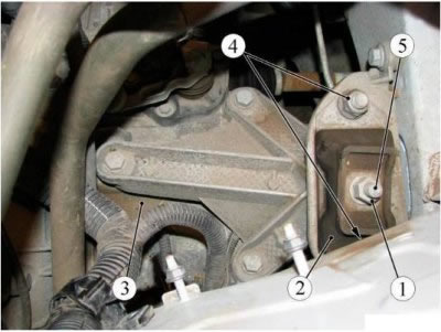
Figure 2-24 - Disconnecting the gearbox from the left engine mount: 1 - a nut of a hairpin of fastening of a transmission; 2 - pillow of the left support of the engine mount; 3 - gearbox; 4 - nut for fastening the left engine mount; 5 - transmission stud
Using a bronze drift, knock out the pin 5 of the gearbox mounting from the cushion of the left suspension support and separate the engine with the gearbox assembly from the cushion of the support (technological bronze drift, hammer).
Unscrew two nuts 4 and remove the pillow of the left engine mount (interchangeable head 18, knob, extension).
Install the transport trolley under the engine with gearbox assembly (trolley for installation and transportation of the engine - self-made).
Lower the vehicle to the level of the transport trolley, install shock-absorbing pads and lower the engine with gearbox assembly onto the trolley, while avoiding damage to attachments (technological gaskets).
Disconnect the crosshead hooks from the lifting eyes.
Raise the vehicle and remove the engine assembly with the gearbox from the engine compartment.
Installation
Operations common to all vehicle configurations
Install the transport trolley with the engine and gearbox assembly under the car (trolley for installation and transportation of the engine - self-made).
Lower the vehicle to the level of the transport cart and install the engine mounts.
Install according to the marks on the body made during removal:
- right engine mount;
- left engine mount.
Install:
- front suspension subframe;
- two bolts securing the steering gear to the front suspension subframe (interchangeable head 18, ratchet knob);
- steering heat shield (for vehicles with K4M engine) (interchangeable head 13, ratchet wrench);
- bolts 1, figure 2-19, upper fastening of the stretch marks of the front suspension subframe (interchangeable head 13, extension, ratchet wrench);
- front wheel drives;
- bolts 7, Figure 2-18, fastening shock absorber struts 5 to steering knuckles 6 (interchangeable head 18, ratchet wrench);
- ball joints of outer tips of 3 steering rods (interchangeable head 16, ratchet wrench);
- front brakes 1 (interchangeable head 18, extension, ratchet wrench).
Tightening torques (torque wrench):
- bolts of fastening of the steering gear to the subframe of the front suspension 105 N.m (10.5 kgf·m) (interchangeable head 18);
- bolts of the upper fastenings of the stretch marks of the front suspension subframe 21 N.m (2.1 kgf·m) (interchangeable head 13);
- shock absorber mounting bolts to the steering knuckle 105 N.m (10.5 kgf·m) (interchangeable head 18);
- nuts of fastening of fingers of spherical joints of tips of steering draughts 37 N.m (3.7 kgf·m) (interchangeable head 16);
- front brake mounting bolts 105 N.m (10.5 kgf·m) (interchangeable head 18).
Install wires "masses" on the gearbox (interchangeable head 13, extension, ratchet knob).
Bolt Torque 1, Figure 2-17, Wire Attachments 2 "masses" on gearbox 21 N.m (2.1 kgf·m) (interchangeable head 13, extension, torque wrench).
Install the exhaust system.
Install the rear engine mount.
For vehicles with JH3 gearbox
Apply MOLYKOTE 33 grease to bolt 2, Figure 2-21, of the transmission control linkage mountings.
Connect the linkage 3 of the gearbox control actuator to the gearbox.
Tightening torque of the bolt for fastening the linkage of the gearbox control drive to the gearbox 27.5 N.m (2.75 kgf·m) (interchangeable head 10, extension, torque wrench).
Install protective cover 1 on the gearshift lever.
Install the clutch cable.
For vehicles with JR5 gearbox
Install the stoppers 3, Figure 2-22, of the sheaths of the select and shift cables to the gearbox bracket.
Connect the hinges 1 of the selector and shift cables to the levers on the gearbox.
Remove the plugs from the openings of the pipeline and the clutch slave cylinder.
Connect the pipeline 1, Figure 2-23, of the clutch hydraulic actuator to the working cylinder 2 by pressing the clamp 4.
Bleed the air from the clutch circuit.
For vehicles with power steering optional
Install the power steering reservoir to the body bracket.
Install and connect the power steering high and low pressure lines.
Connect connector 2, Figure 2-6, of the wiring harness to the pressure sensor in the power steering system.
Operations common to all vehicle configurations
Install the coolant hoses in the holder.
Connect hoses 2, Figure 2-15, engine cooling systems with new clamps (clamp pliers Mot. 1202-02):
- to the thermostat housing 3;
- to the coolant supply pipe;
- to the radiator of the engine cooling system.
Join:
- brake booster vacuum hose to intake manifold;
- crankcase ventilation hose to intake manifold;
- fuel supply line 1, Figure 2-14, to fuel rail 2;
- block of the wiring harness to the canister purge solenoid valve;
- retainer 2, Figure 2-13, throttle cable sheath;
- ball tip 1 of the drive cable to the throttle valve block;
- wiring harness pads 3, Figure 2-5, to electric fan 4 of the engine cooling system;
- wiring harness to cooling fan.
Replace the gasket on drain plug 1 and fit the plug with a new gasket. Drain plug tightening torque 22 N.m (2.2 kgf·m) (wrench for an internal square 8 mm, replaceable nozzle for an internal square 8 mm, torque wrench).
Loosen the filler plug.
Pour oil into the gearbox. The oil level must reach the lower edge of the filler hole (filling station S-223-1, gear oil in accordance with the current "Codifier of the main and auxiliary materials used in the maintenance and repair of LADA vehicles" K 3100.25100.00018-2008, filling rate: for JH3 - 2.8 l; for JR5 - 2.5 l).
Install the filler plug.
Pour fluid into the cooling system.
For vehicles with air conditioning optional
Remove the technological plugs and connect the pipeline to the air conditioning compressor.
Connect connector 1, Figure 2-12, of the wiring harness to the refrigerant pressure sensor 2.
For vehicles with K4M engine additionally:
- connect the hose of the fuel vapor recovery system;
- install the front bumper.
Operations common to all vehicle configurations
Install the hub nuts using the tool. Tightening torque of the hub fastening nut 280 N.m (28.0 kgf·m) (Rou device. 604-01, interchangeable head 32, knob, torque wrench).
Install:
- side mudguards and linings;
- engine crankcase protection;
- front wheels;
- injection computer.
Install:
- fuse holders and relay sockets in box 1, Figure 2-4, relays and fuses;
- fuse and relay box cover.
Install the engine wire harness 3 into the holder on the shelf under the battery.
For vehicles with K4M engine
Install block 3, Figure 2-3, throttle body.
Install protection 2 for the fuel rail.
Install intake silencer 1.
For vehicles with K7M engine
Install housing 3, Figure 2-2, of the air filter.
Operations common to all vehicle configurations
Install air intake pipe 1.
Install the battery tray.
Install battery 2.
For vehicles with power steering optional
Fill the power steering system with working fluid (power steering oil Mobil ATF 52475).
Bleed air from the power steering system by turning the steering wheel from the left end position to the right end position.
Start the engine and bleed the air from the power steering system by turning the steering wheel from the left end position to the right end position.
Top up the fluid level in the power steering pump reservoir.
Make sure there is no fluid leakage.
Operations common to all vehicle configurations
Remove air from the engine cooling system.
For vehicles with air conditioning optional
Charge refrigerant into the air conditioning circuit.