
Removing
Operations common to all vehicle configurations.
Put the car on a two-post lift, apply the parking brake, turn off the ignition and disconnect the wire terminal "masses" from the battery.
For vehicles with K4M engine
Remove the right front wheel.
Remove the right side mudguard.
Remove the accessory drive belt.
Remove the crankshaft pulley.
Remove the right engine mount.
Remove timing belt.
Remove intake silencer.
Remove the air filter housing.
Remove throttle body.
Remove intake manifold.
Remove the camshaft seals from the timing side.
Remove ignition coils.
Disconnect hose 1, Figure 9-1, crankcase breather from oil separator 2.
Loosen the eight mounting screws (interchangeable head 8, extension, crank).
Separate oil separator 2 from cylinder head cover 4 (flat screwdriver).
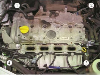
Figure 9-1 - Removing the oil separator and lifting eye: 1 - crankcase ventilation hose; 2 - oil separator; 3 - lifting eye; 4 - cylinder head cover
Remove bolts 1, Figure 9-2, fastening the cylinder head cover (interchangeable head 8, extension, ratchet wrench).
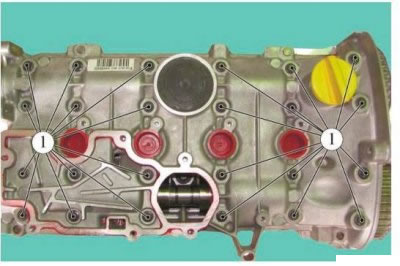
Figure 9-2 - Removing the cylinder head cover of the K4M engine: 1 - bolts of fastening of a cover of a head of cylinders
Separate the cylinder head cover by pulling it up and tapping on the tabs with a bronze drift (technological drift).
Remove cylinder head cover.
For vehicles with K7M engine
Remove housing 1, Figure 9-3, of the air filter.
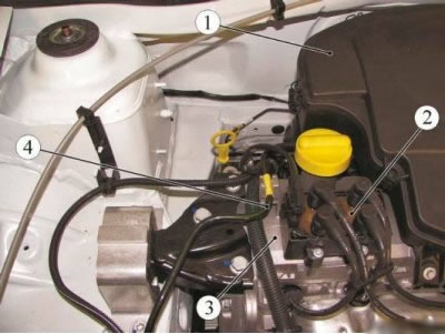
Figure 9-3 - Removing the cylinder head cover of the K7M engine: 1 - air filter housing; 2 - ignition module; 3 - cylinder head cover; 4 - tube of the gasoline vapor recovery system
Remove ignition module 2.
Detach pipe 4 for EVAP system from holder on cylinder head cover.
Disconnect pipe 1, Figure 9-4, and crankcase breather hose 2 from cylinder head cover.
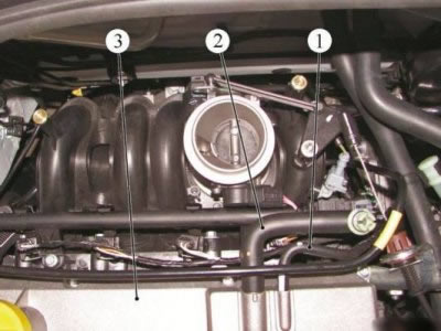
Figure 9-4 - Disconnecting the crankcase ventilation hose: 1 - crankcase ventilation tube; 2 - crankcase ventilation hose; 3 - cylinder head cover
Remove bolts 1, Figure 9-4, fastening the cylinder head cover (interchangeable head 8, extension, ratchet wrench).
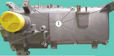
Figure 9-5 - Removing the cylinder head cover: 1 - a bolt of fastening of a cover of a head of cylinders
Remove cylinder head cover.
Remove the cylinder head cover gasket.
Installation
For vehicles with K4M engine
About using sealant instead of a gasket: Building motors with sealants is easier, faster and cheaper. There is no need to purchase additional product numbers. Moreover, some types of sealants have advantages over rubber, if used correctly.
There are several types of sealants. The most famous is silicone, capable of filling cavities up to 6 millimeters, retaining its properties and elasticity for a long time during operation.
In addition, silicone holds high pressure well, which allows it to be used in highly accelerated engines. The only subtle point is that the mating surfaces must be thoroughly degreased before application. One of the most popular in industrial assembly is an anaerobic sealant. It can only be applied to relatively flat surfaces, but it is convenient to work with it. There are a number of compounds, such as synthetic and polyurethane sealants, but they are more likely to be universal types.
Clean the cylinder head and head cover from sealant residues.
Degrease mating surfaces of cylinder head and cylinder head cover (brush, white spirit).
Apply MASTIXO sealant with a paint roller, Figure 9-6 (paint roller, sealant MASTIXO part number 77 11 428 232).
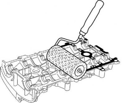
Figure 9-6 - Applying sealant to the cylinder head cover of the K4M engine
Remove the sealant from the working surfaces of the bearings in the cylinder head cover (rag).
Install the cylinder head cover.
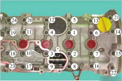
Figure 9-7 - The order of tightening the bolts of the cylinder head cover of the K4M engine: 1...24 - bolts of fastening of a cover of a head of cylinders
Install and tighten bolts 1... 24, Figure 9-7, securing the cylinder head cover in the indicated order in several stages (interchangeable head 8, extension, torque wrench):
- 1st stage - bolts 22, 23, 20 and 13 with a tightening torque of 8 Nm (0.8 kgf·m);
- 2nd stage - bolts 1 - 12, 14 - 19, 21 and 24 tightening torque 15 Nm (1.5 kgf·m);
- 3rd stage - loosen bolts 22, 23, 20 and 13;
Install the lifting eye 3, Figure 9-1, of the engine on the flywheel side of the cylinder head cover. Bolt tightening torque 11 Nm (1.1 kgf·m) (interchangeable head 16, torque wrench).
Clean oil separator 2 of sealant residues.
Degrease the mating surfaces of the cylinder head cover and oil separator (brush, white spirit).
Apply MASTIXO sealant to the oil separator using a paint roller according to Figure 9-8 (paint roller, sealant MASTIXO part number 77 11 428 232).
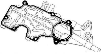
Figure 9-8 - Applying sealant to the oil separator of the K4M engine
Install the oil separator.
Install and tighten bolts 1... 8, Figure 9-9, fixing the oil separator in the specified order. Tightening torque for oil separator mounting bolts 15 Nm (1.5 kgf·m) (interchangeable head 8, extension, torque wrench):
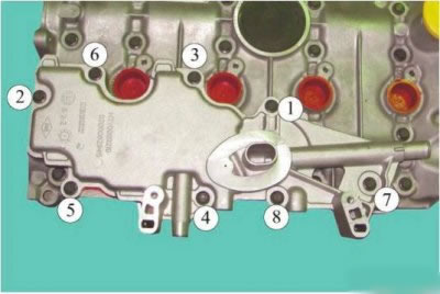
Figure 9-9 - The order of tightening the bolts for fastening the oil separator of the K4M engine: 1...8 - oil separator mounting bolts
Connect hose 1, Figure 9-1, crankcase breather to oil separator 2. Install ignition coils.
Install intake manifold.
Install the throttle body.
Install the air filter housing.
Install the intake silencer.
Install the timing belt.
Install the right engine mount.
Install the crankshaft pulley.
Install the accessory drive belt.
Install the right side mudguard.
Install the right front wheel.
For vehicles with K7M engine
Clean the mating surface of the cylinder head cover.
Attention. The cylinder head cover gasket must be replaced. Install the cylinder head cover with a new gasket.
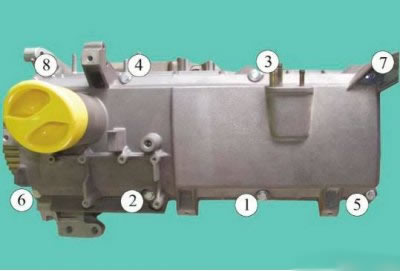
Figure 9-10 - The order of tightening the bolts of the cylinder head cover of the K7M engine: 1...8 - bolts of fastening of a cover of a head of cylinders
Install and tighten bolts 1...8, Figure 9-10, securing the cylinder head cover in the specified order in two stages (interchangeable head 8, extension, torque wrench):
- 1st stage - tightening torque 2 Nm (0.2 kgf·m);
- 2nd stage - tightening torque 10 Nm (1.0 kgf·m).
Connect tube 1, Figure 9-4, and hose 2 for crankcase ventilation to cylinder head cover 3.
Connect pipe 4, Figure 9-3, of the gasoline vapor recovery system to the holder on the cylinder head cover.
Install ignition module 2.
Install air cleaner housing 1.
Operations common to all vehicle configurations.
Attach wire terminal "masses" to the battery.