



Removal
Place the vehicle on a two-post lift, apply the parking brake and turn off the ignition (electro-hydraulic lift type P-3.2G with a lifting capacity of 3.2 t).
For vehicles with air conditioning
Perform a complete discharge of the refrigerant from the air conditioning system in accordance with the requirements of TI 3100.25100.20600 and the operating instructions for the service equipment.
For all vehicle trim levels
Disengage the loops securing the rear seat cushion to the body and tilt the cushion forward.
Remove the electric fuel pump hatch cover.
Disconnect connector 1, Figure 3-1, of the rear wiring harness from module 2 of the electric fuel pump.
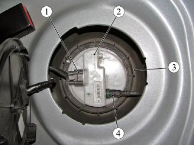
Figure 3-1 - Electric fuel pump module: 1 - rear wiring harness connector to the electric fuel pump module; 2 - electric fuel pump module; 3 - fuel tank; 4 - fuel pipe tip
Start the engine and let it run at idle speed until it stops completely to relieve pressure in the fuel system, ensuring the removal of exhaust gases (exhaust reel with fan type SERF/SP). Turn off the ignition.
Connect the wiring harness connector to the electric fuel pump module.
Install the electric fuel pump hatch cover.
Lower the rear seat cushion and secure the cushion loops into the mounting brackets on the body.
Remove the storage battery (AKB) 1, Figure 3-2, in accordance with the requirements of TI 3100.25100.20597.
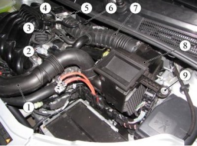
Figure 3-2 - Battery (s): 1 - battery; 2, 5 - nut; 3 - terminal of the "ground" wire; 4 - terminal of the "+" wire; 6 - bolt; 7 - pressure bar
Remove the intake module screen.
Loosen clamp 3, Figure 3-3, of the fastening and disconnect the upper hose 2 of the crankcase ventilation from the branch pipe of the cylinder head cover (pliers).
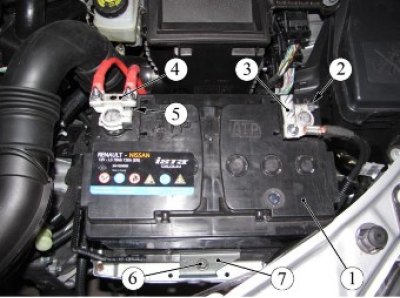
Figure 3-3 - Air cleaner with air supply pipe and intake pipe hose assembly (on a car with an H4M engine): 1 - air supply pipe; 2 - Upper crankcase ventilation hose; 3 - Upper crankcase ventilation hose clamp; 4 - throttle pipe; 5 - intake pipe hose clamp; 6 - brake booster hose; 7 - Inlet pipe hose; 8 - air filter; 9 - air filter mounting bolt
Loosen clamp 5 and disconnect hose 7 of the intake pipe from throttle pipe 4 (flat head screwdriver).
Press the latches and disconnect the air supply pipe from the air intake.
For cars with H4M engine
Loosen bolt 9, Figure 3-3, securing the air filter and remove air filter 8 with air supply pipe 1 and intake pipe hose 7 as an assembly (replacement head 10, ratchet).
For cars with engines 21129 and 21179
Unscrew the two bolts 1, Figure 3-4, securing the resonator to the bracket 3 on the car body (replacement head 10, ratchet).
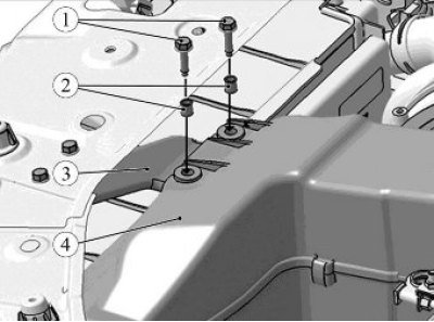
Figure 3-4 - Resonator mounting: 1 - resonator mounting bolt; 2 - bushing; 3 - resonator mounting bracket; 4 - resonator
Loosen the bolt securing the air filter to the bracket on the car body and remove the air filter with the resonator and the intake pipe hose assembly (replacement head 10, ratchet).
For all vehicle trim levels
Unscrew nut 2, Figure 3-5, securing bracket 1 of the engine wiring harness to bracket 3 of the air filter and move the wiring harness to the side (replacement head 10, extension, ratchet).
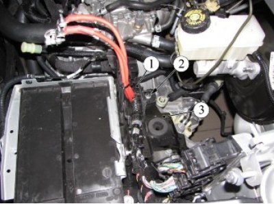
Figure 3-5 - Engine Wiring Harness Securing: 1 - Engine wiring harness bracket; 2 - nut; 3 - Air filter bracket
Unscrew the three nuts 1, Figure 3-6, fastenings and remove the air filter bracket 2 (replacement head 10, extension, ratchet).
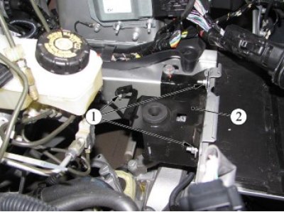
Figure 3-6 - Air filter bracket mounting: 1 - nut; 2 - Air filter bracket For cars with H4M engine
Disconnect the tip of tube 1, Figure 3-7, of the adsorber valve and the tube itself from the inlet module 2.
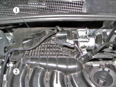
Figure 3-7 - Installing the adsorber valve tube on the H4M engine: 1 - adsorber valve tube; 2 - intake module
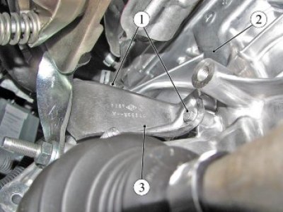
Figure 3-8 - Installing the crankshaft position sensor protective screen on the H4M engine: 1 - bolt; 2 - cylinder block; 3 - protective screen of the crankshaft position sensor
Disconnect the engine wiring harness connectors and pads from the connectors:
- unscrew the two bolts 1, figure 3-8, fastenings, remove the protective screen 2 and disconnect the harness connector from the crankshaft position sensor (replacement head 10, ratchet wrench);
- sensor 1, figure 3-9, absolute pressure;
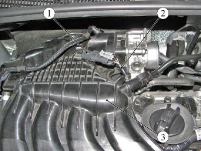
Figure 3-9 - Installing the absolute pressure sensor on the H4M engine: 1 - absolute pressure sensor; 2 - Engine wiring harness; 3 - intake module
- sensor 1, figure 3-10, intake air temperature;
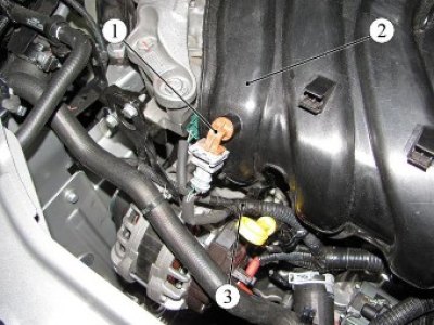
Figure 3-10 - Installing the intake air temperature sensor on the H4M engine: 1 - intake air temperature sensor; 2 - intake module; 3 - Engine wiring harness
- throttle pipe 1, figure 3-11;
- connectors 1 and 2, figure 3-12, wiring harness of injectors and ignition coils;
- 3 phase sensor;
- 4 oxygen content sensors;
- coolant temperature sensor 5;
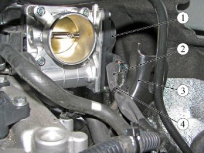
Figure 3-11 - Throttle body on the H4M engine: 1 - throttle pipe; 2 - Engine wiring harness; 3 - engine bracket; 4 - Wiring harness mounting clamp
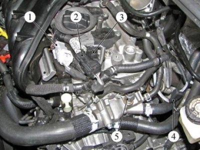
Figure 3-12 - H4M engine wiring harness connections: 1, 2 - connector of the wiring harness of injectors and ignition coils; 3 - phase sensor connector; 4 - oxygen content sensor; 5 - coolant temperature sensor
- sensor 1, figure 3-13, oil pressure indicator lamp;
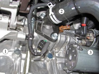
Figure 3-13 - Connections of the H4M engine wiring harness with sensors: 1 - oil pressure warning light sensor; 2 - Engine wiring harness; 3 - knock sensor
- knock sensor 3;
- valve 1, figure 3-14, camshaft position adjustment;
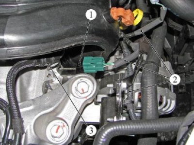
Figure 3-14 - Connecting the wiring harness of the H4M engine to the phase adjustment valve: 1 - phase adjustment valve; 2 - Engine wiring harness; 3 - fuel pipe tip
- reverse light switch on the gearbox.
For cars with engines 21129 and 21179
Disconnect tip 1, Figure 3-15, of the adsorber valve tube and the tube itself from inlet module 2.
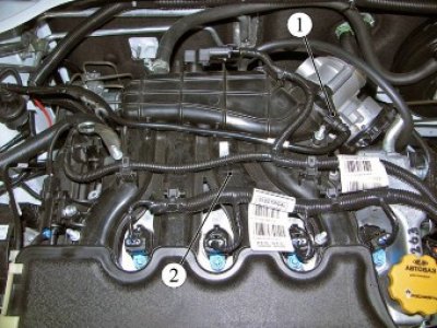
Figure 3-15 - Installing the canister valve tube on engine 21129: 1 - tip of the adsorber valve tube; 2 - intake module
Disconnect the engine wiring harness connectors and pads from the connectors:
- sensor 1, figure 3-16, crankshaft position;
- sensor 1, figure 3-17, air pressure and temperature;
- valve 2 intake manifold flap (for engine 21129);
- throttle pipe 1, figure 3-18;
- 2 oxygen content sensors;
- coolant temperature sensor 3;
- harness 5 wires injectors;
- sensor 6 oil pressure warning lamp;
- harness 7 wires ignition coils;
- camshaft position control valve (for engine 21179);
- reverse light switch on the gearbox.
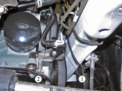
Figure 3-16 - Installing the crankshaft position sensor on engines 21129 and 21179: 1 - crankshaft position sensor; 2 - Engine wiring harness
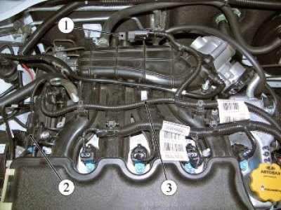
Figure 3-17 - Installing the air pressure and temperature sensor and the intake manifold flap valve on engine 21129: 1 - air pressure and temperature sensor; 2 - intake manifold flap valve; 3 - Engine wiring harness
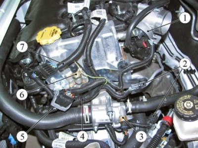
Figure 3-18 - Engine 21129 Wiring Harness Connections: 1 - throttle pipe; 2 - oxygen sensor connector; 3 - coolant temperature sensor; 4 - Engine wiring harness; 5 - injector wiring harness; 6 - Oil pressure warning light sensor; 7 - ignition coil wiring harness
For cars with AMT
Additionally, disconnect the engine wiring harness connectors:
- from the actuator for selecting and shifting gears;
- from the clutch actuator.
For all vehicle trim levels
Loosen the mounting bolts, disconnect the brackets and clamps, cut the mounting clamps and move the engine wiring harness to the side (replaceable head 8, 10, extension, ratchet, flat screwdriver, pliers, technological knife).
Remove the front wheels in accordance with the requirements of TI 3100.25100.20594.
Remove the engine mudguard in accordance with the requirements of TI 3100.25100.20594.
Remove the inner linings and the left side mudguard in accordance with the requirements of TI 3100.25100.20599.
Remove the front suspension subframe with the front suspension arms, anti-roll bar, steering rack and electric power steering pump as an assembly in accordance with the requirements of TI 3100.25100.20594.
For vehicles with manual transmission
Disconnect the ends 2 of the gear shift cable and 3 of the gear selector cable from the levers 1, Fig. 3-19, of the gear shift mechanism using tool 67.7812-9707 (67.7812-9707 gear shift cable end remover, hammer);
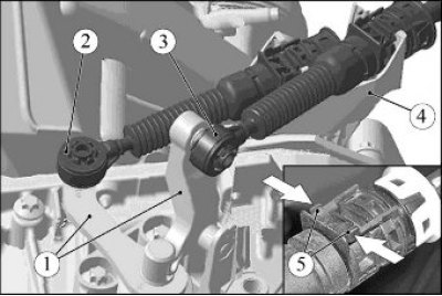
Figure 3-19 - Disconnecting the gear shift cables: 1 - gear shift levers; 2 - gear shift cable tip; 3 - gear selection cable tip; 4 - gear shift cable mounting bracket; 5 - retainer antennae
Press on both sides of the 5 clamps and disconnect the cable sheath stoppers from bracket 4 on the gearbox.
Disconnect the clutch hydraulic line from the slave cylinder.
For vehicles equipped with JH3 gearbox and H4M engine
Raise the retainer 3, Figure 3-20, up until the retainer's antennae rest against the ribs "A", remove the clutch hydraulic drive tube 5 from the working cylinder 1 and install technological plugs on the tube in the opening of the clutch working cylinder. When performing this operation, the lock 4 must remain in the recessed position (technological plugs).
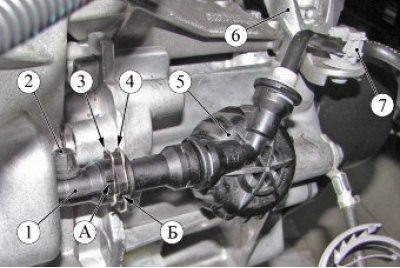
Figure 3-20 - Clutch hydraulic line on the JH3 gearbox: 1 - clutch working cylinder; 2 - protective cap for air bleed nipple; 3, 4 - retainer; 5 - clutch hydraulic tube with receiver assembly; 6 - left engine support bracket; 7 - clutch hydraulic tube mounting bracket; A, B - rib, limiter of the latch stroke
Remove the clutch hydraulic drive tube 5 from the mounting bracket 7 and remove the tube from the work area.
For vehicles equipped with JR5 gearbox and 21129 engine
Press the lock 3, Figure 3-21, remove the tube 6 of the clutch hydraulic drive from the working cylinder 1 and install technological plugs on the tube and in the hole of the clutch working cylinder (technological plugs).
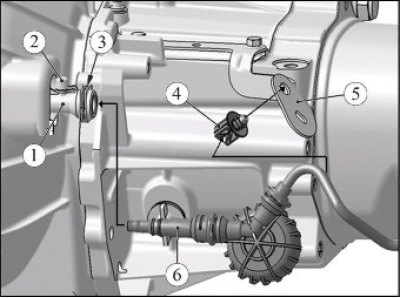
Figure 3-21 - Clutch hydraulic line on the JR5 gearbox: 1 - clutch working cylinder; 2 - protective cap for air bleed nipple; 3 - retainer; 4 - clutch hydraulic tube mounting bracket; 5 - bracket; 6 - clutch hydraulic tube with receiver assembly
Remove the clutch hydraulic drive tube 6 from the mounting bracket 4 and remove the tube from the work area.
For cars with H4M engine
Remove the protective cap 1 from the starter terminal, Figure 3-22, unscrew the two nuts and disconnect the terminals of the wiring harness 2 from the starter traction relay 4 of the engine (replaceable head 8, 10, extension, ratchet wrench).
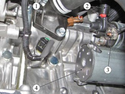
Figure 3-22 - Connecting the engine wiring harness terminals to the starter on the H4M engine: 1 - protective cap; screw; 2 - Engine wiring harness; 3 - nut; 4 - starter
For cars with engines 21129 and 21179
Loosen nut 1, Figure 3-23, and disconnect terminal 2 and connector 3 of the engine wiring harness from the starter traction relay 4 (replaceable head 13, extension, ratchet wrench).
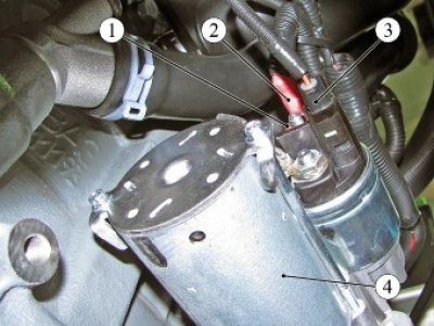
Figure 3-23 - Connecting the terminal and the connector of the engine wiring harness to the starter on engines 21129 and 21179: 1 - nut; 2 - terminal of the engine wiring harness to the starter; 3 - Engine wiring harness connector to starter; 4 - starter
For cars of all trim levels
Drain the coolant in accordance with the requirements of Section 10 of this technological instruction.
For cars with H4M engine
Press the clamps and disconnect the tip of tube 1, Figure 3-24, of the fuel line from the rail 2 of the injectors.
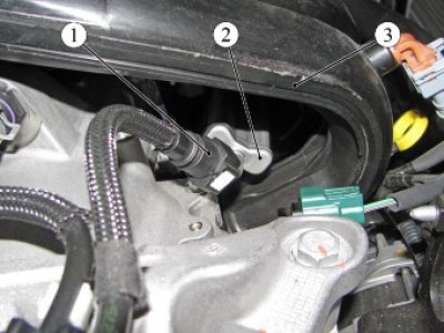
Figure 3-24 - Connection of fuel pipes on the H4M engine: 1 - fuel line tube; 2 - fuel rail; 3 - intake module
For cars with engines 21129 and 21179
Press the clamps and disconnect the tip of tube 1, Figure 3-25, of the intermediate fuel line from tube 2 of the front fuel line and the bracket 3 securing the lines on the intake module 4.
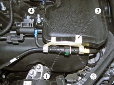
Figure 3-25 - Fuel line connections on engine 21129: 1 - intermediate fuel line tube; 2 - front fuel line pipe; 3 - Pipeline fastening bracket; 4 - intake module
Source link - website: LadaMan.ru
For cars with H4M engine
Loosen clamps 1 and 3, Figure 3-26, and disconnect the supply 4 and outlet 5 hoses of the heater, the supply 6 of the radiator from the coolant outlet pipes of the housing 2 (pliers).
Loosen clamps 1 and 3, Figure 3-27, and disconnect the filling hose 4 of the cooling system and the outlet hose 5 of the radiator from the pipes of the housing 2 of the thermostat and the cylinder block (pliers).
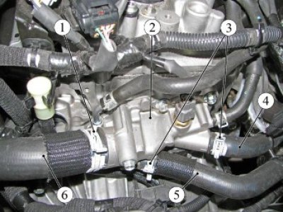
Figure 3-26 - Coolant outlet housing and cooling system hoses of the H4M engine: 1, 3 - clamp; 2 - coolant outlet housing; 4 - heater supply hose; 5 - heater outlet hose; 6 - radiator supply hose
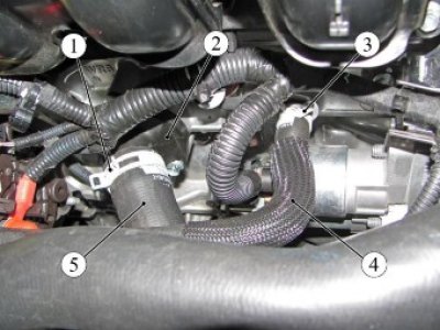
Figure 3-27 - Thermostat and hoses of the cooling system of the H4M engine: 1, 3 - clamp; 2 - thermostat housing; 4 - cooling system filling hose; 5 - radiator outlet hose
For cars with engines 21129 and 21179
Loosen the clamps and disconnect the radiator supply hose 9 and the heater supply hose 4 from the thermostat 2, Figure 3-28 (pliers).
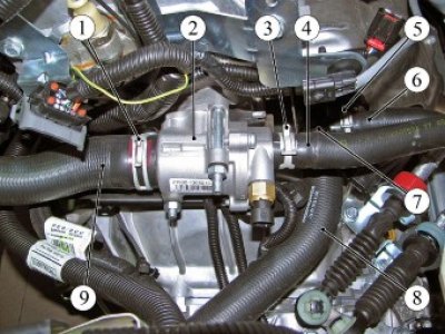
Figure 3-28 - Thermostat and engine cooling system hoses 21129: 1, 3, 5, 7 - clamp; 2 - thermostat; 4 - heater supply hose; 6 - heater outlet hose; 8 - radiator outlet hose; 9 - radiator supply hose
Loosen the clamps and disconnect the outlet 6 heater hose and outlet 8 radiator hose from the water pump inlet pipe (pliers).
Loosen clamp 1, Figure 3-29, and disconnect filler hose 3 from water pump supply pipe 2 (pliers).
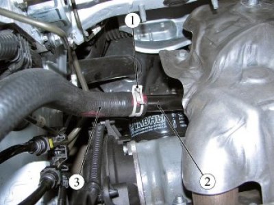
Figure 3-29 - Engine cooling system filler hose: 1 - clamp; 2 - water pump supply pipe; 3 - filling hose
Operations are common for all vehicle configurations
Disconnect the engine wiring harness from the generator, for which it is necessary:
- remove protective cap 1, figure 3-30;
- unscrew the fastening nut and disconnect terminal 2 of the engine wiring harness from the generator (replacement head 13, extension, ratchet);
- disconnect connector 3 of the engine wiring harness to the generator.
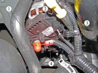
Figure 3-30 - Connecting the Engine Wiring Harness to the Generator: 1 - protective cap; 2 - generator; 3 - Engine wiring harness connector to the generator; 4 - terminal of the engine wiring harness to the generator
For vehicles with manual transmission
Loosen bolt 2, Figure 3-31, securing terminal 1 of the ground wire to the manual transmission and disconnect the terminal (replaceable head 13, extension, ratchet wrench).
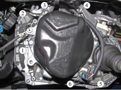
Figure 3-31 - Fastening the ground wire harness terminal and the engine wire harness connector to the manual transmission: 1 - terminal of the "ground" wire; 2 - bolt; 3 - 5th gear cover; 4 - wiring harness mounting bracket; 5 - Engine wiring harness connector to reverse light switch; 6 - Reverse light switch
For cars with AMT
Unscrew nut 1, Figure 3-32, securing terminal 2 of the ground wire on AMT 3 and disconnect the terminal (replaceable head 17, extension, ratchet wrench).
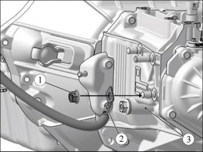
Figure 3-32 - Fastening the terminal of the ground wire harness to the AMT: 1 - nut; 2 - terminal of the "ground" wire; 3 - AMT
For cars with engines 21129 and 21179
Loosen clamp 1, Figure 3-33, and disconnect hose 2 of the brake booster from module 3 of the intake manifold (phillips screwdriver).
For vehicles with H4M engine
Disconnect tip 1, Figure 3-34, of brake booster tube 2 from intake module 3.
For cars with air conditioning
Loosen the two bolts 1, Figure 3-35, securing the pipelines 2 to the compressor 3 of the air conditioning system and disconnect the pipelines (replaceable head 8, ratchet wrench).
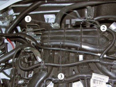
Figure 3-33 - Brake booster hose on engine 21129: 1 - clamp; 2 - brake booster hose; 3 - intake module
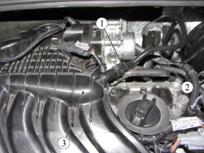
Figure 3-34 - Brake booster tube on the H4M engine: 1 - brake booster tube tip; 2 - brake booster tube; 3 - intake module
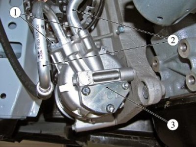
Figure 3-35 - Air conditioning compressor: 1 - bolt; 2 - air conditioning system pipelines; 3 - Air conditioning compressor
Install technological plugs on the pipelines and in the compressor openings (technological plugs).
POWER UNIT - REMOVAL - PART 5
Lada X-Ray. POWER UNIT - REMOVAL - PART 5
Operations are common for all vehicle configurations
Unscrew plug 1, Figure 3-36, of the drain hole in the 3-speed gearbox housing and drain the oil (8 mm internal square wrench or 17 mm ring wrench, type 24164 installation by ALFA (Italy) for collecting used oil).
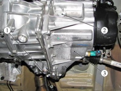
Figure 3-36 - Draining the gearbox oil:
1 - drain plug;
2 - filler plug;
3 - gearbox
For vehicles with manual transmission JH3 and JR5
Install the plug into the oil drain hole in the gearbox housing. Tightening torque of the plug 19...25 Nm (1.9...2.5 kgf·m) (8mm internal square wrench, torque wrench).
For cars with AMT 2182
Degrease the threads in the gearbox housing and on the plug, apply sealant to the threaded part of the plug (white spirit, consumption rate 2 g; sealant PS-1 according to the current "Codifier of main and auxiliary materials used in maintenance and repair of LADA vehicles" K 3100.25100.00018, consumption rate 1 g).
Install the plug into the oil drain hole in the gearbox housing. Tightening torque of the plug 29.46 N·m (2.9...4.6 kgf·m) (replaceable head 17, ratchet, torque wrench).
Operations are common for all vehicle configurations
Remove the rear support of the powertrain suspension in accordance with the requirements of Section 11 of this TI.
Knock out and remove the inner joints of drives 1 and 3, Figure 3-37, of the front wheels from the gears of the differential axle shafts of the 2nd gearbox in accordance with the requirements of TI 3100.25100.20593.
Disconnect the exhaust system from the engine and body in accordance with the requirements of Section 9 of this TI.
Move the exhaust pipe towards the rear of the car and hang it on the body (technological hooks).
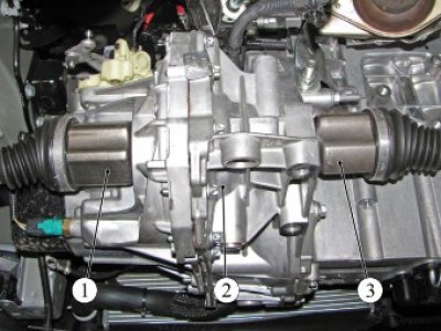
Figure 3-37 - Front wheel drives: 1 - left wheel drive; 2 - gearbox; 3 - right wheel drive
Bring the crane 1, Figure 3-38, hydraulic to the vehicle, insert the hooks of the lifting clamp 2 into the eyes of the lifting eyes 3 of the power unit and hang out the power unit 4 (hydraulic crane type OMA-587, grip TCO 3/379.000).
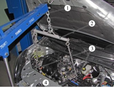
Figure 3-38 - Hanging the power unit: 1 - hydraulic crane; 2 - lifting grip; 3 - eye; 4 - power unit
Unscrew the two nuts 1, Figure 3-39, securing the power unit to the left support 2 of the power unit suspension (replacement head 18, extension, ratchet).
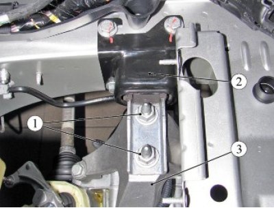
Figure 3-39 - Left powertrain mount: 1 - nut; 2 - left support of the power unit suspension; 3 - left bracket of the power unit suspension
For vehicles with H4M engine
Loosen and remove three bolts 1, Figure 3-40, securing the power unit to the right support 2 of the power unit suspension (replacement head 16, extension, ratchet).
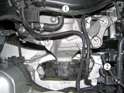
Figure 3-40 - Right support of the power unit suspension with the N4M engine: 1 - bolt; 2 - right support of the power unit suspension
For cars with engines 21129 and 21179
Loosen and remove the two bolts 1, Figure 3-41, securing the power unit to the right support 2 of the power unit suspension (torx E12 replaceable head, extension, ratchet).
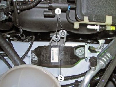
Figure 3-41 - Right support of the power unit suspension with engines 21129 and 21179: 1 - bolt; 2 - right support of the power unit suspension
Install a transport trolley under the engine and gearbox assembly (trolley type 67.50.004).
Lower the vehicle to the level of the transport trolley, install shock-absorbing pads and lower the engine with gearbox assembly onto the trolley, while excluding damage to the attachments (technological gaskets).
Disconnect the lifting hooks from the lifting eyes.
Raise the vehicle and remove the engine and gearbox assembly from the engine compartment.