
Comment. Depending on the purpose of the work, the steering column can be removed complete with the steering wheel and steering column switches. The operation is shown with partial disassembly of the steering column.
Removing
1. We prepare the car for work and remove the terminal from the negative terminal of the battery (see «Preparing the car for maintenance and repair»).
2. Turn the steering wheel to the position corresponding to the movement in a straight line. Removing the steering wheel (see «Steering wheel - removal and installation»)
3. Remove the decorative lining of the steering column (see «Decorative overlays of a steering column - removal and installation»).
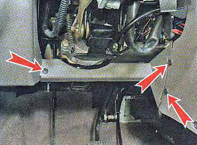
4. Using a Phillips screwdriver, unscrew the three screws and remove the lower trim of the instrument panel.
5. Disconnect the wiring harness pads from the steering column switches and slip ring (see «Paddle switches - removal, inspection and installation»).
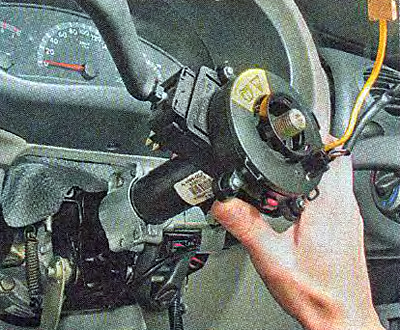
6. Loosen the coupling bolt with an 8 mm spanner (see «Paddle switches - removal, inspection and installation») and remove the connector assembly with steering column switches and slip ring»).
7. Disconnect the ignition switch wiring harness pads (see «Switch (lock) ignition - removal and installation»).
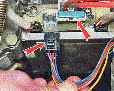
8. Releasing the clamps, disconnect the two pads of the wiring harnesses from the electric power steering.
Comment. You can remove the steering column assembly with the intermediate shaft. However, it is more convenient to remove and install the steering column if you disconnect the intermediate shaft. The connection of the flanges of the universal joints of the intermediate shaft is possible only in one position, so you can not mark their relative position.
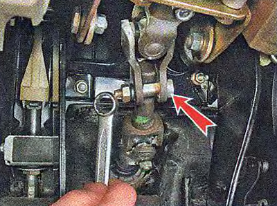
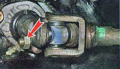
9. Using a 13 mm spanner, unscrew the nut of the coupling bolt connecting the universal joints of the intermediate shaft. We take out the bolt.
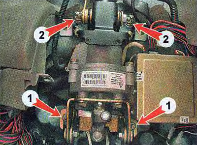
10. Using a 13 mm socket wrench, we loosen the tightening of two nuts 1 of the lower mounting of the steering column. Using the same wrench, unscrew the two nuts 2 of the upper mounting of the steering column.
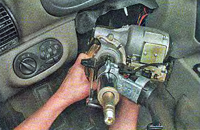
11. Remove the steering column assembly.
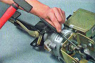
12. Using a 13 mm spanner, unscrew the nut of the coupling bolt of the flange of the lower universal joint of the intermediate shaft. We take out the bolt.
13. Open the flange with a slotted screwdriver and remove the cardan joint from the splines of the steering gear shaft.
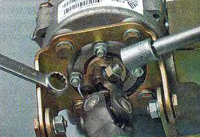
14. With a marker or other available method, we mark the relative position of the flange of the upper universal joint and the steering shaft. Using a 13 mm socket wrench, unscrew the nut of the coupling bolt, holding the bolt head with a spanner wrench of the same size.
15. Through the beard we knock down the cardan joint from the splines of the steering shaft.
Installation
Install the steering column in reverse order. Before installation, make sure that the front wheels are in the straight ahead position, and the groove on the shaft where the mark on the steering gear housing cover, as well as the marks on the protective cover, are properly located (see photo).
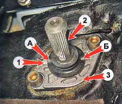
The location of the marks for setting the steering shaft to the position of the rectilinear movement of the vehicle:
1 - angular recess in the cover of the crankcase of the steering mechanism;
2 - groove on the shaft of the steering mechanism;
3 - cover of the crankcase of the steering mechanism;
A - angular protrusion on the protective cover;
B - cutout in the edge of the protective cover.
The protective cover must be put on the steering gear shaft so that the mark A is located opposite the angular shape recess 1 located in the crankcase cover, and the shaft is rotated so that its groove 2 is located opposite the mark B of the protective cover.
We tighten the nuts of the coupling bolts on the flanges of the intermediate shaft with a torque of 23-28 Nm (2.3-2.8 kgf·m). We tighten the steering column mounting nuts with a torque of 15-18.6 Nm (1.5-1.9 kgf·m).