



The outer constant velocity joint consists of a housing 1, a separator 5, an inner race 3 and six balls 6. Grooves for accommodating the balls are made in the housing of the constant velocity joint and in the race. The grooves in the longitudinal plane are made along the radius, which provides an angle of rotation of the outer joint of up to 42°. The splined tip of the constant velocity joint housing is installed in the hub of the front wheel and secured to it with a nut.
The sleeve 3 of the joint is installed on the splines of the shaft 12 between the thrust ring 7 and the retaining ring 2.
The internal constant velocity joint differs from the external one in that the tracks of the housing and the collar are made straight, not radial, which allows the joint parts to move in the longitudinal direction. This is necessary to compensate for movements caused by vibrations of the front suspension and power unit.
The outer and inner constant velocity joints are equipped with balls of the same sorting group; if necessary, all six balls of the joint are replaced, which must also be of the same sorting group. When assembling the inner constant velocity joint, a selective method is used. Replacing any one part is not allowed - the internal constant velocity joint must be replaced as an assembly.
The parts of constant velocity joints are lubricated with SHRUS-4 grease, which is placed in the joint housings during assembly. Sealing of the hinges is ensured by protective covers 8 and 13, secured with clamps 4 and 9. To prevent deformation of the covers due to changes in internal air pressure during assembly of the hinge and during operation, valves 10 for air passage are installed on the covers in casings 11.
Helpful advice. The drive joints are very durable, their estimated service life is almost equal to the service life of the car. However, during operation they are often changed or repaired. This work is expensive and labor-intensive. To save a lot of money, regularly check the condition of the hinge covers and replace them immediately if they show any damage. If water or dust gets into the joint through a damaged cover, it will fail after several hundred kilometers. The sealed joint wears out extremely slowly.
Possible faults of front wheel drives, their causes and methods of elimination | |
| Cause of malfunction | Method of elimination |
| Noise, knocking from the front wheel when the car is moving | |
| Wear of constant velocity joint components Deformation of the drive shafts of the wheels | Replace worn or damaged constant velocity joints Replace the drive shafts |
| Lubricant leak | |
| Damage or rupture of the protective cover of the inner or outer hinges | Replace the grease in the hinge and the protective cover |
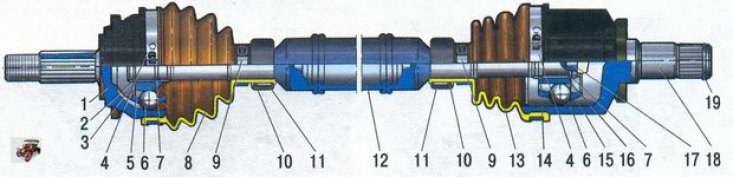
Figure 5.8. Front wheel drive: 1 - outer hinge housing; 2 - retaining ring of the hinge sleeve; 3 - outer hinge cage; 4 - clamp for fastening the cover to the hinge body; 5 - outer joint separator; 6 - inner joint ball; 7 - thrust ring of the hinge cage; 8 - outer hinge cover; 9 - cover fastening clamp; 10 - cover valve; 11 - valve cover casing; 12 - front wheel drive shaft; 13 - inner hinge cover; 14 - inner hinge lock; 15 - inner joint separator; 16 - inner joint cage; 17 - shaft buffer; 18 - inner hinge housing; 19 - retaining ring