
The cooling system is filled with ethylene glycol based coolant (antifreeze, antifreeze), not freezing at ambient temperatures down to -40°C.
Water pump 10 (pic. 4.8) centrifugal type provides forced circulation of coolant in the cooling system, is installed on the front plane of the cylinder block and is driven by a timing belt of the camshaft drive. The water pump has sealed bearings that do not need to be relubricated. The water pump is not subject to repair, in case of failure (coolant leak or bearing damage) it is replaced as an assembly.
Thermostat 5 with a solid temperature-sensitive filler maintains the normal operating temperature of the coolant and reduces the warm-up time of the engine on the car. The thermostat has a main and an additional (bypass) valves. At coolant temperatures up to (85±2) °С the thermostat is completely closed and the liquid circulates through a small circuit, bypassing the radiator, which accelerates the engine warm-up. At a temperature (85+2) °C, the thermostat starts to open, and at 102°C it comes off completely, circulating coolant through the radiator.
electric fan engine cooling 9 (pic. 4.9) with a plastic six-bladed impeller, it ensures the radiator is blown with air at low vehicle speeds, mainly in urban areas or on mountain roads, when the oncoming air flow is insufficient to cool the radiator.
To improve the efficiency of the engine cooling fan installed in the casing 7 and attached to it at three points through the rubber pads. The casing, in turn, is attached to the radiator 3 at four points.
The engine control unit controls the cooling fan, which receives information about the coolant temperature from sensor 6 (see fig. 4.8), located in the thermostat socket 5.
Radiator 3 (see fig. 4.9) tubular-lamellar, aluminum, with plastic tanks, two-way, with a partition in the left tank. In the lower part of the right tank there is a drain plug 5. In the radiator tanks there are inlet and outlet hose pipes to the engine water jacket and a hose pipe connecting the radiator to the expansion tank.
The expansion tank 12 serves to compensate for the changing volume of the coolant depending on its temperature. The expansion tank is made of translucent plastic. The walls of the expansion tank are marked «MAX» And «MIN» to control the level of the coolant, there is a filler neck on top, hermetically sealed with a plastic plug 1 with two valves inside it (inlet and outlet), collected in a single block. Exhaust valve opens at 110 kPa (1.1 kgf/cm2), providing an increase in the temperature of the start of boiling of the coolant and preventing intense vaporization. When the liquid cools, the volume of the coolant decreases and a vacuum is created in the engine cooling system. The inlet valve in the plug of the expansion tank opens at a vacuum of about 3 kPa (0.03 kgf/cm2) and the inlet valve in the plug lets air into the expansion tank.
The interior heater radiator is included in the engine cooling system with hoses.
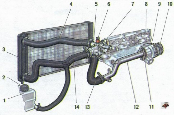
Pic. 4.8. Engine cooling system: 1 - expansion tank; 2 - plug of the expansion tank; 3 - radiator of the engine cooling system; 4 - radiator inlet hose; 5 - thermostat; 6 - coolant temperature sensor of the engine management system; 7 - thermostat gasket; 8 - cylinder head; 9 - water pump gasket; 10 - water pump; 11 - laying the supply pipe; 12 - inlet pipe of the water pump; 13 - hose from the thermostat to the inlet pipe of the water pump; 14 - radiator outlet hose assembly
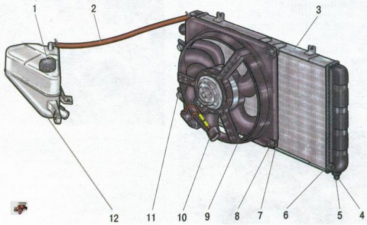
Pic. 4.9. Radiator with electric fan and expansion tank: 1 - plug of the expansion tank; 2 - steam outlet hose; 3 - radiator; 4 - radiator support cushion; 5 - sealing ring of the drain plug; 6 - drain plug; 7 - casing of the electric fan; 8 - nut; 9 - electric fan; 10 - electric fan wiring harness connector; 11 - bolt; 12 - expansion tank