
The system is filled with ethylene glycol based coolant (antifreeze), which does not freeze at ambient temperatures down to -40°С.
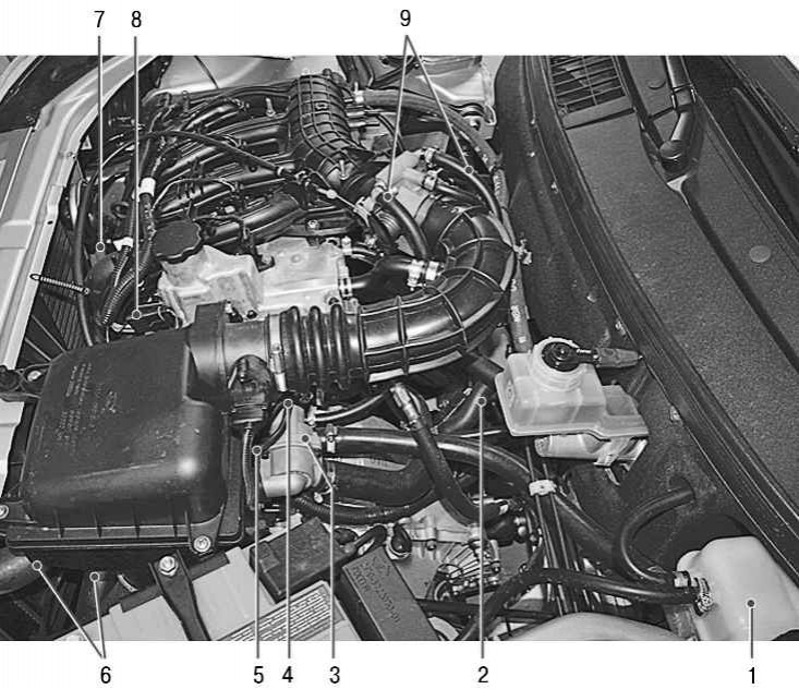
Pic. 5.16. Location of cooling system elements: 1 - expansion tank; 2 – heater hoses; 3 - thermostat; 4 – the gauge of the index of temperature of a cooling liquid (not visible in the photo, located under the thermostat); 5 - coolant temperature sensor; 6 - radiator hoses; 7 – a stopper of a drain aperture of a radiator; 8 – plug of a drain opening of the block of cylinders; 9 - throttle assembly heating hoses
The location of the elements of the cooling system is shown in fig. 5.16.
Note. The procedure for replacing the coolant is described at the beginning of Sec. 4 «Maintenance».
Attention! It is not recommended to fill the cooling system with water, as antifreeze contains anti-corrosion and anti-foaming additives, as well as additives that prevent scale build-up.
Warning! Coolant is toxic! Avoid inhalation of vapors and contact with skin.
Warning! Timely eliminate the violation of the tightness of the cooling system in order to avoid the ingress of coolant vapor into the vehicle interior during its operation. Your health is more valuable than a new cooling system pipe or a tube of sealant!
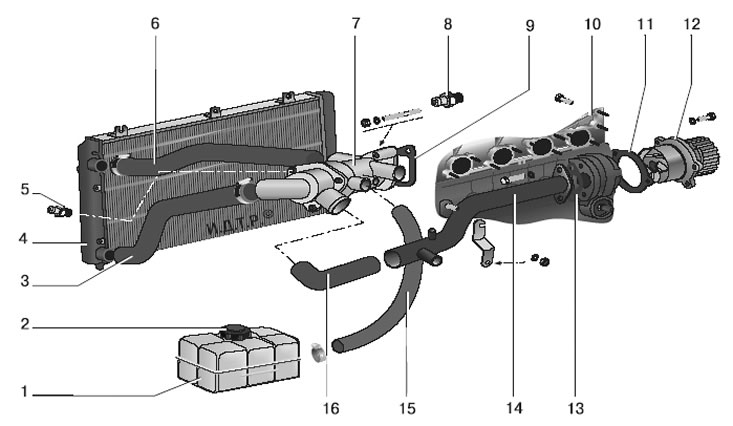
Pic. 5.17. Cooling system: 1 - expansion tank; 2 – a stopper of a broad tank; 3 - outlet hose of the radiator; 4 - radiator of the engine cooling system; 5 - coolant temperature sensor of the engine management system; 6 - the inlet hose of the radiator; 7 - thermostat; 8 – gauge of the indicator temperature of a cooling liquid; 9 - thermostat gasket; 10 – a head of the block of cylinders; 11 - water pump gasket; 12 - water pump; 13 - laying the supply pipe; 14 - inlet pipe of the water pump; 15 - filling hose; 16 - hose from the thermostat to the inlet pipe of the water pump
The device of the cooling system is shown in fig. 5.17.
Water pump 12 (see fig. 5.17) centrifugal type provides forced circulation of fluid in the cooling system, is installed on the front plane of the cylinder block and is driven by a timing belt of the camshaft drive. The pump has sealed bearings that do not require relubrication. The pump is not subject to repair, in case of failure (fluid leakage or bearing damage) it is replaced as an assembly.
Thermostat 7 with a solid heat-sensitive filler maintains the normal operating temperature of the coolant and reduces the warm-up time of the engine. It has a primary and secondary (bypass) valves. At coolant temperatures up to (85±2) °С the thermostat is completely closed and the liquid circulates through a small circuit, bypassing the radiator, which accelerates the engine warm-up. At a temperature (85±2) °C the thermostat begins to open, and at 102°C it comes off completely, providing fluid circulation through the radiator.
electric fan 15 (pic. 5.18) with a plastic four-bladed impeller, it ensures the radiator is blown with air at low vehicle speeds, mainly in urban areas or on mountain roads, when the oncoming air flow is insufficient to cool the radiator.
To increase the efficiency of work, the fan is installed in the casing 8 and attached to it at three points through rubber cushions. The casing, in turn, is attached to the radiator 4 at four points.
The electric fan is controlled by the engine control unit, which receives information about the coolant temperature from sensor 5 (see fig. 5.17), located in the thermostat socket 7.
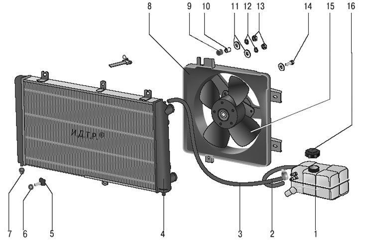
Pic. 5.18. Radiator with electric fan and expansion tank: 1 - expansion tank; 2 - steam outlet hose of the heater radiator; 3 - steam outlet hose of the radiator of the cooling system; 4 - radiator; 5 - drain plug; 6 - sealing ring of the drain plug; 7 – a pillow of a support of a radiator; 8 - casing of the electric fan; 9 - elastic sleeve; 10 - remote bushing; 11 - washer; 12 - spring washer; 13 - nut; 14 - bolt; 15 - electric fan; 16 – a stopper of a broad tank
Radiator 4 (see fig. 5.18) tubular-lamellar, aluminum, with plastic tanks, two-way, with a partition in the left tank. In the lower part of the right tank there is a drain plug 5. The tanks have inlet and outlet hose pipes to the engine water jacket and a hose pipe connecting the radiator to the expansion tank.
Expansion tank 1 serves to compensate for the changing volume of the coolant depending on its temperature. The tank is made of translucent plastic. Marked on its walls «MAX» And «MIN» to control the level of the coolant, there is a filler neck on top, hermetically sealed with a plastic plug 16 with two valves inside it (inlet and outlet), collected in a single block. Exhaust valve opens at 110 kPa (1.1 kgf/cm2), providing an increase in the temperature of the start of boiling of the coolant and preventing intense vaporization. When the liquid is cooled, its volume decreases and a vacuum is created in the system. The inlet valve in the plug opens at a vacuum of about 3 kPa (0.03 kgf/cm2) and lets air into the expansion tank.
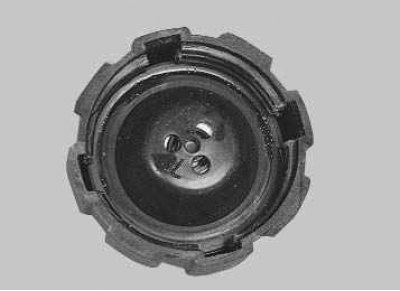
Note. The serviceability of plug valves is very important for the normal operation of the cooling system, but often when problems occur (boiling of coolant, etc.) motorists pay attention only to the operation of the thermostat, forgetting to check the valves. Leakage of the exhaust valve leads to a decrease in the boiling point of the coolant, and its jamming in the closed state leads to an emergency increase in pressure in the system, which can cause damage to the radiator and hoses.
The interior heater radiator is included in the cooling system with hoses.
Possible malfunctions of the cooling system, their causes and remedies are given in the table.