
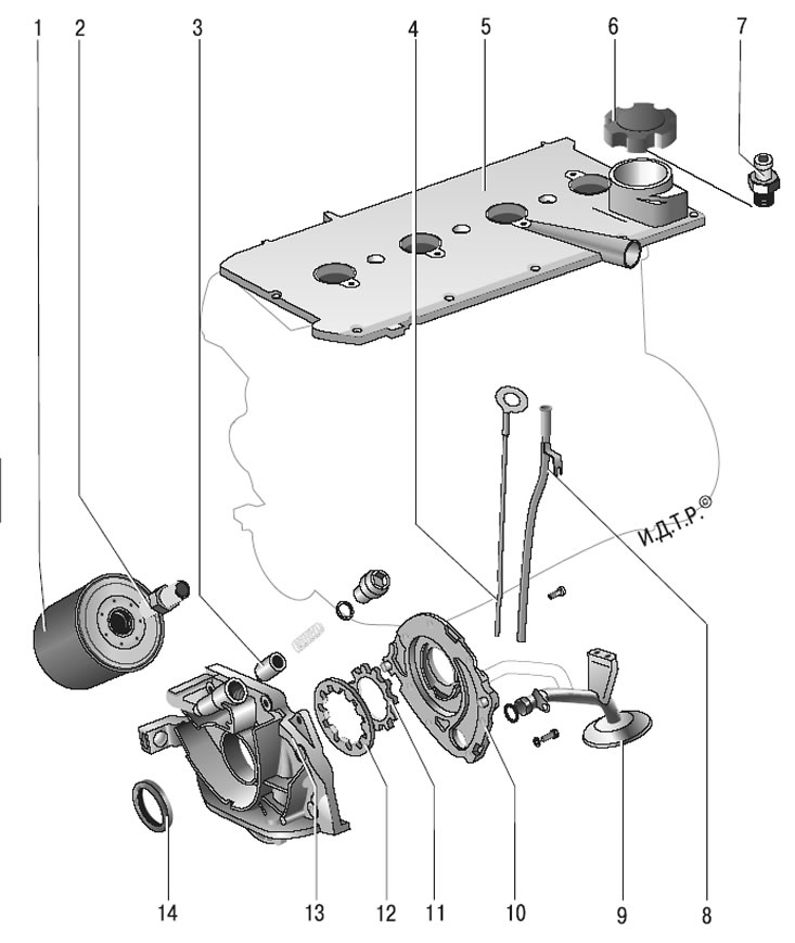
Pic. 5.15. Lubrication system: 1 - oil filter; 2 - oil filter fitting; 3 - pressure reducing valve; 4 - oil dipstick; 5 – a cover of a head of the block of cylinders; 6 - oil filler cap; 7 - sensor signal lamp emergency drop in oil pressure; 8 - guide tube of the oil dipstick; 9 - oil receiver; 10 - oil pump housing; 11 - oil pump drive gear; 12 - driven gear of the oil pump; 13 - oil pump cover; 14 - stuffing box
The device of the lubrication system is shown in fig. 5.15.
Combined lubrication system: main and connecting rod bearings of the crankshaft, camshaft bearings are lubricated under pressure; splashing - cylinder walls, pistons with piston rings, piston pins, camshaft cams, pushers and valve stems.
The system consists of an oil sump, a gear oil pump with an oil receiver 9, a full-flow oil filter 1, an oil pressure sensor 7 and oil channels.
When the oil pressure drops below the permissible value, the oil pressure warning lamp lights up in the instrument cluster.
The gear oil pump, with gears 11 and 12 of internal gearing, is located on the front end of the cylinder block. The drive gear 11 of the oil pump is mounted on two flats at the front end of the crankshaft. To reduce mechanical losses, the gears have trochoidal meshing. The oil receiver 9 is bolted to the cover of the second main bearing and to the pump housing. To limit the maximum pressure in the lubrication system, a pressure reducing valve 3 is installed on the pump.
Oil filter 1 full-flow, non-separable, with bypass and anti-drain valves.
Work on changing the engine oil and oil filter is described in Sec. «Maintenance»; removal and installation, as well as repair of the oil pump - in this subsection.