
The engine cooling system uses special liquids based on a mixture of water and ethylene glycol. They have a low freezing point and a high boiling point. In addition, thanks to the complex of added additives, the coolant prevents corrosion of the channel walls, does not foam, and prolongs the life of the coolant pump seal.
The circulation of liquid in the system is provided by a centrifugal pump installed in the cylinder block. The pump is driven by a toothed timing belt.
The cooling system consists of two so-called circulation circles. The small circle does not include the engine radiator, and the liquid washes only the cylinder block and cylinder head, and also flows through the throttle assembly channel and the heater radiator. The heater radiator is built into the engine cooling system and is designed to heat the passenger compartment by circulating hot coolant through it. When driving in a large circle, the coolant passes through the engine radiator, where it is cooled by the oncoming air flow. The thermostat controls the direction of fluid flow in the engine cooling system. It has two valves - main and bypass (additional). The main valve controls the circulation of liquid in a large circle, and the bypass valve in a small one. The valves are interconnected: when one opens, the second closes, and vice versa.
Cold bypass (additional) the thermostat valve is open, and the liquid circulates only in a small circle. At a temperature of about 87°C, the main valve of the thermostat begins to open, and the bypass valve closes, and for some time the liquid circulates in small and large circles at the same time. At a temperature of 102°C, the main thermostat valve is fully open and the bypass valve is closed, and all fluid flow passes through the engine radiator. If the air flow is insufficiently intense, the radiator is cooled by an electric fan. It is installed behind the engine radiator and is activated by a signal from the electronic engine control unit. An additional resistor is built into the power supply circuit of the fan motor.
To compensate for the thermal expansion of the liquid, an expansion tank is installed in the cooling system. Inlet and outlet safety valves are placed in the tank plug, which allows maintaining the optimal pressure in the system when the liquid is heated, as well as compensating for the vacuum when it cools.
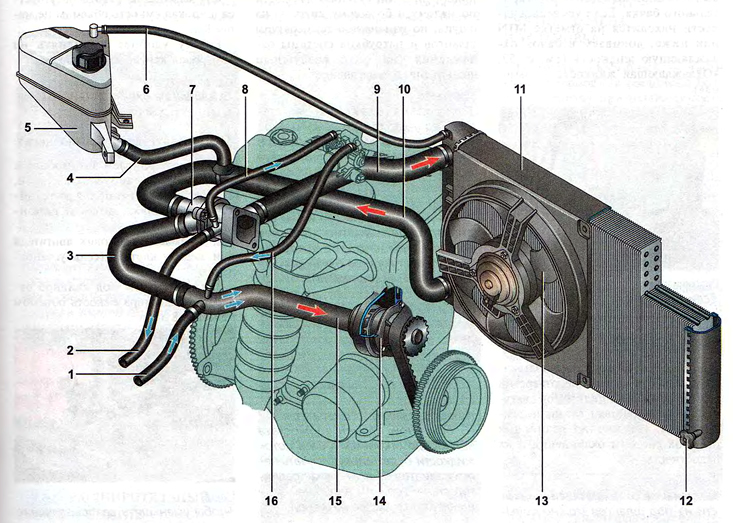
Cooling system:
1 - hose for draining coolant from the heater radiator;
2 - hose for supplying coolant to the heater radiator;
3 - hose of the supply pipe of the coolant pump;
4 - expansion tank hose;
5 - expansion tank;
6 - steam outlet hose of the engine radiator;
7 - thermostat;
8 - hose for supplying fluid to the throttle assembly;
9 - hose for supplying fluid to the engine radiator;
10 - hose for draining fluid from the engine radiator;
11 - engine radiator;
12 - radiator drain plug;
13 - radiator electric fan;
14 - coolant pump;
15 - inlet pipe of the coolant pump;
16 - coolant outlet hose from the throttle assembly.