



The air entering the engine cylinders is cleaned of dust by the air filter. The air filter is installed in the engine compartment on three rubber supports. The filter element is replaceable and made of special paper. To prevent contaminated air from being sucked into the intake tract, there is a sealing edging at the top of the element. To replace the filter element, the filter cover is removable. The purified air passes through the mass air flow sensor through the air duct to the throttle valve.
The throttle valve regulates the amount of air entering the engine cylinders. The drive of the valve from the gas pedal is cable. The valve rotates on the axis in the housing (pipe). The throttle valve housing is fixed to the flange of the intake module on studs. The housing has a channel for cooling liquid. The channel is connected to the cooling system by rubber hoses. Circulation of coolant through the throttle body prevents freezing of the internal air cavities of the body in winter. The housing contains fittings for connection to the adsorber and the engine crankcase ventilation system.
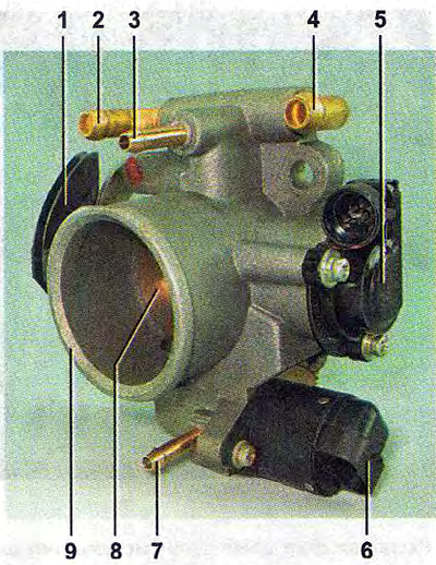
Throttle assembly:
1 - throttle actuator sector;
2, 4 - nipples for connection to the engine cooling system;
3 - crankcase gas supply nipple;
5 - throttle position sensor;
6 - idle speed controller;
7 - nipple for connection to the adsorber;
8 - throttle valve;
9 - throttle body pipe.
The throttle body with the throttle position sensor and idle speed controller installed on it form the throttle assembly.
The fuel supply is stored in a 50-liter tank. The fuel tank is made of steel, welded from two stamped parts. The tank is suspended from the bottom of the car using two steel clamps. The fuel tank filler neck is located on the right side of the vehicle and is closed with a plug. Fuel is supplied from the tank by a submersible electric fuel pump.
The pump is installed in the fuel tank. To access the pump, there is a hatch with a cover in the bottom of the car under the rear seat cushions.
A mesh filter is installed on the inlet pipe of the fuel pump, which traps small solid particles of debris that enter the fuel tank along with gasoline. Voltage is supplied to the pump by command from the ECU when the ignition is turned on. If no attempt is made to start the engine, then after 2-3 seconds the ECU will turn off the fuel pump*
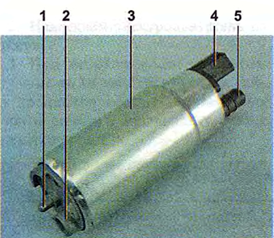
Fuel pump:
1 - protrusion for fastening the mesh filter;
2 - fuel intake pipe for connecting a mesh filter;
3 - body;
4 - Electrical connector block;
5 - day off (forcing) branch pipe for connection to the fuel module cover with a corrugated tube.
From the pump, through the corrugated tube of the fuel module (see below), gasoline enters the fuel line and then into the fuel filter, where the fuel undergoes more thorough cleaning.
The fuel filter is paper and is installed in a non-separable metal housing.
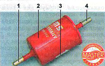
Fuel filter:
1 - inlet pipe;
2 - body;
3 - fuel flow direction arrow (painted on the filter body);
4 - outlet pipe.
The purified fuel enters the fuel rail through the fuel line.
The fuel rail holds four injectors and supplies fuel to them. The connection between the ramp and the injectors is sealed with rubber rings. The ramp is secured to the cylinder head with bolts.
The fuel pressure regulator is a bypass valve that maintains pressure in the system (fuel line) operating pressure 378-390 kPa, necessary for the correct operation of the injection system.
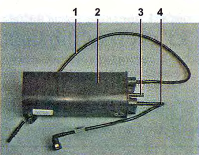
Adsorber:
1 - pipe connecting the adsorber to the separator;
2 - adsorber body;
3 - branch pipe for connecting the internal cavity of the adsorber with the atmosphere;
4 - tube for connecting the adsorber to the adsorber purge valve.
In accordance with current environmental requirements, the vehicle is equipped with a fuel vapor recovery system; the space above the fuel tank is not directly connected to the atmosphere, but through elements of this system. The system consists of a separator, an adsorber, an adsorber purge valve, connecting tubes and hoses. The separator is attached under the left rear wing of the car. In the separator, gasoline vapors are partially condensed and returned through the filler pipe back to the fuel tank.
From the separator, uncondensed gasoline vapors are fed through pipes and connecting hoses to the adsorber, which prevents the vapors from entering the atmosphere. An adsorber is a container where gasoline vapors are absorbed by activated carbon. When the engine is running at high crankshaft speed, the ECU sends a signal to open the purge valve of the adsorber, and gasoline vapors are sucked into the receiver of the intake module.
The adsorber is attached to the fuel tank on the left and is covered with a protective screen.
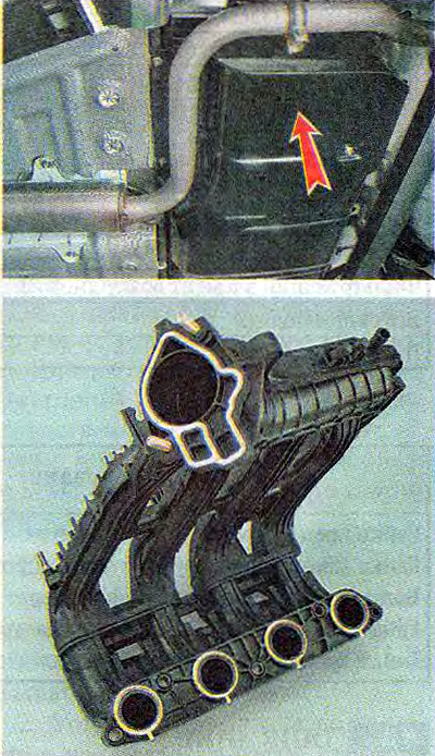
Intake module
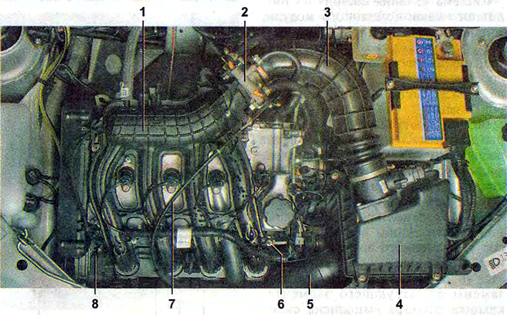
Location of engine fuel system components in the engine compartment:
1 - inlet module;
2 - throttle assembly;
3 - air supply hose to the throttle valve;
4 - air filter;
5 - air intake;
6 - fuel rail;
7 - throttle cable;
8 - fuel rail diagnostic connector.
Note: Engine with decorative trim removed.
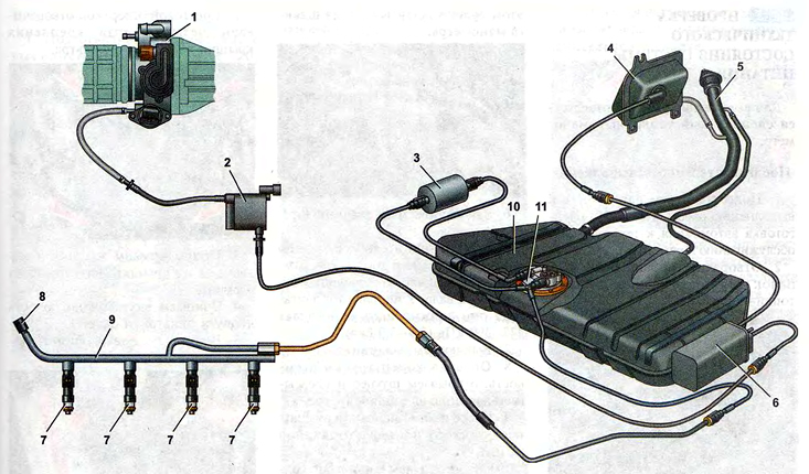
Engine power supply system diagram:
1 - throttle assembly;
2 - purge valve of the adsorber;
3 - fuel filter;
4 - separator;
5 - filler pipe;
6 - adsorber;
7 - injectors;
8 - fuel rail diagnostic connector;
9 - fuel rail;
10 - fuel tank;
11 - fuel module.
Air is supplied to the intake valves of the engine cylinders through the intake module.
The engine intake module is made of special plastic and is a non-separable element.
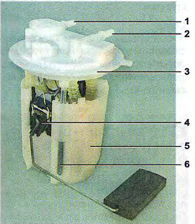
Engine fuel module:
1 - inlet pipe (for supplying fuel to the pressure regulator);
2 - day off (forcing) pipe branch;
3 - module cover;
4 - fuel level indicator sensor;
5 - intake chamber;
6 - module cover guide.
The filler cap has two valves: one for emergency release of fuel vapor pressure from the tank (what is possible with an increase in ambient temperature), and the other one is for the intake of air from the atmosphere when fuel is consumed from the tank (this eliminates the occurrence of a strong vacuum in the tank).
The fuel pump is combined with the fuel level indicator sensor and the fuel pressure regulator into a single unit - the fuel module (often called an electric fuel pump).
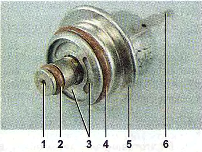
Engine Fuel Pressure Regulator:
1 - hole for draining excess fuel;
2, 4 - sealing rings;
3 - holes for supplying fuel to the regulator;
5 - body;
6 - terminal for connecting the regulator to ground.
Fuel from the pump (through the outlet pipe of the fuel module) enters the fuel filter. The purified gasoline is again fed through the fuel line and through the tee to the inlet pipe of the fuel module and then fed into the fuel rail. Excess fuel is released through the pressure regulator into the tank. The fuel pressure regulator is installed in the fuel module cover.
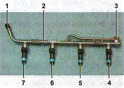
Fuel rail of the engine complete with injectors:
1 - diagnostic nipple (for checking the working pressure, closed with a threaded cap);
2 - fuel rail;
3 - nipple for connection to the fuel line;
4, 5, 6 and 7 - injectors.