
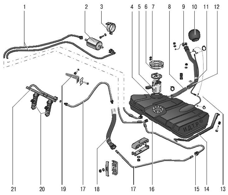
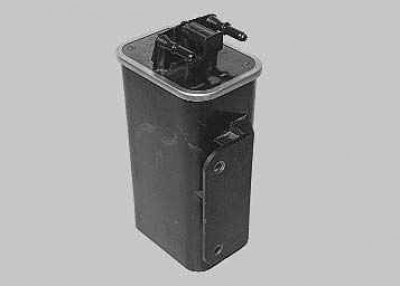
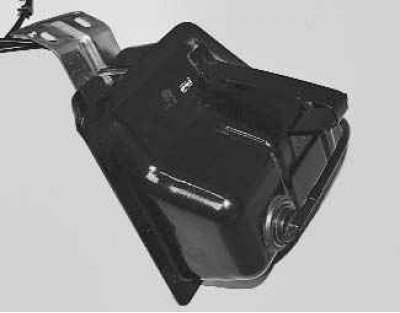
Pic. 5.19. Fuel supply system: 1 - fuel pipes (plastic); 2 - fuel filter; 3 – an arm of fastening of the fuel filter; 4 – a sealing ring of the fuel pump; 5 - fuel pump; 6 - distance ring; 7 – a clamping ring of fastening of the fuel pump; 8 – a hose of a filling pipe; 9 – stopper of a bulk pipe of a fuel tank; 10 - lining of the neck of the filling pipe; 11 - clamp; 12 – a bulk pipe of a fuel tank; 13 - air outlet hose; 14 – a collar of fastening of a fuel tank; 15 - connector (quick connector); 16 – fuel tank; 17 - fuel pipes (metal); 18 - fuel supply hose; 19 - bracket; 20 - nozzles; 21 - fuel rail
Fuel supply system including fuel tank 16 (pic. 5.19), fuel pump 5 with integrated fuel pressure regulator, fuel pipes 1 and 17, hose 18, fuel rail 2 (pic. 5.20) with 1 injectors as well as 2 fuel filter (see fig. 5.19);
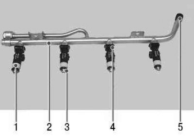
Pic. 5.20. Fuel rail and injectors: 1 - nozzle; 2 - fuel rail; 3 - sealing ring; 4 - nozzle retainer; 5 – a cap of the union for fuel pressure control
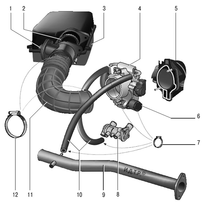
Pic. 5.21. Air supply system: 1 - mass air flow sensor; 2 - sealing sleeve; 3 - air filter; 4 - throttle assembly; 5 - intake manifold; 6 - idle speed regulator or additional air regulator; 7 - hose clamps; 8 - thermostat; 9 - inlet pipe of the coolant pump; 10 - hoses for heating the throttle assembly; 11 - air supply sleeve; 12 - clamps for fastening the air supply sleeve
Air supply system consisting of 3 air filter (pic. 5.21), air supply sleeve 11, throttle assembly 4;
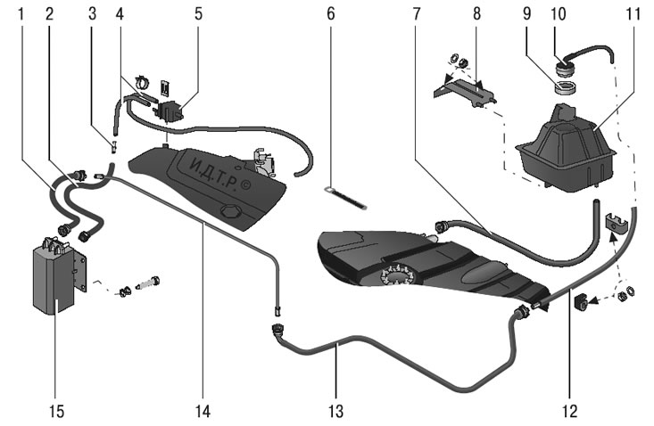
Pic. 5.22. Evaporative Emission System: 1 - front steam pipe; 2 - adsorber tube and purge valve; 3 - adapter; 4 - hoses; 5 – adsorber purge valve; 6 - clamp; 7 - fuel drain pipe; 8 – separator bracket; 9 - valve gasket; 10 - gravity valve; 11 – fuel vapor separator; 12 - rear steam pipe; 13 – medium steam pipe; 14 – steam pipeline tube; 15 - adsorber
Fuel vapor recovery system including adsorber 15 (pic. 5.22), canister purge valve 5, fuel vapor separator 11, gravity valve 10, connecting steam lines 1, 2, 12, 13, 14 and hoses 4.
The functional purpose of the fuel supply system is to ensure the supply of the required amount of fuel to the engine in all operating modes. The engine is equipped with an electronic control system with distributed fuel injection. In the distributed fuel injection system, the functions of mixture formation and dosing of the air-fuel mixture supply to the engine cylinders are separated: the nozzles carry out metered fuel injection into the intake pipe, and the amount of air required at each moment of engine operation is supplied by a system consisting of a throttle assembly and an idle speed controller. This control method makes it possible to ensure the optimal composition of the combustible mixture at each particular moment of engine operation, which allows obtaining maximum power with the lowest possible fuel consumption and low exhaust gas toxicity. Manages the fuel injection system and the ignition system electronic control unit (ECU) engine, which continuously monitors, with the help of appropriate sensors, the amount of engine load, the speed of the vehicle, the thermal state of the engine, and the optimality of the combustion process in the engine cylinders.
A feature of the injection system of the VAZ-2170 Lada Priora is the synchronous operation of the nozzles in accordance with the valve timing (the engine control unit receives information from the phase sensor). The controller turns on the injectors sequentially, and not in pairs or simultaneously, as in asynchronous injection systems. Each nozzle is activated through 720°of crankshaft rotation. However, in start-up and dynamic modes of engine operation, an asynchronous method of fuel supply is used without synchronization with the rotation of the crankshaft.
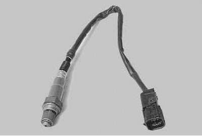
The main sensor for the fuel injection system is oxygen concentration sensor in exhaust gases (Lambda probe). It is installed in the engine exhaust manifold and, together with the engine control unit and injectors, forms a control loop for the composition of the air-fuel mixture supplied to the engine. Based on the sensor signals, the engine control unit determines the amount of unburned oxygen in the exhaust gases and, accordingly, evaluates the optimal composition of the air-fuel mixture entering the engine cylinders at any given time. Having fixed the deviation of the composition from the optimal 1:14 (fuel: air), providing the most efficient operation of the catalytic converter of exhaust gases, the control unit changes the composition of the mixture using injectors. Since the oxygen concentration sensor is included in the feedback circuit of the engine control unit, the air-fuel ratio control loop is closed. A feature of the engine control system of the VAZ-2170 Lada Priora is the presence, in addition to the control sensor, of a second, diagnostic oxygen concentration sensor installed at the outlet of the converter. According to the composition of the gases that have passed through the converter, it determines the efficiency of its work.
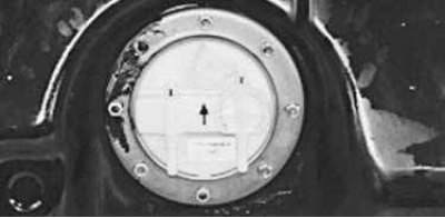
Fuel tank 16 (see fig. 5.19) welded, stamped, installed under the floor of the body in its rear part and secured with two steel clamps 14. To prevent fuel vapor from entering the atmosphere, the tank is connected through a fuel vapor separator 11 (see fig. 5.22) and a gravity valve 10 with steam lines 12, 13, 14 and 1 with an adsorber 15. An electrical module of an electric fuel pump is installed in the flange hole in the upper part of the tank (fuel pump) 5 (see fig. 5.19), which combines the pump itself, the fuel gauge sensor and the fuel pressure regulator. A branch pipe is made in the rear part of the tank for connecting a filling pipe 12. From the pump, fuel is supplied to the fuel filter 2, installed from below on the base of the body, and from there it enters the fuel rail 21, mounted on the engine cylinder head. From the fuel rail, fuel is injected by injectors 20 into the inlet channels of the cylinder head, and the fuel jet is directed to the inlet valve. Excess fuel is drained into the fuel tank through the fuel pressure regulator installed in the fuel pump module. Such a scheme for installing a fuel pressure regulator, in addition to eliminating a long backflow pipeline, makes it possible to prevent an increase in the temperature of the fuel in the tank, which causes excessive vaporization.
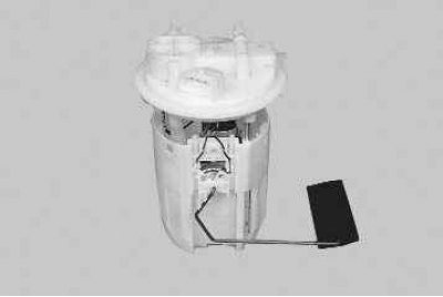
Fuel pump (fuel pump module) 5 (see fig. 5.19) submersible, vortex type, with a coarse fuel filter. The pump provides fuel supply and is installed in the fuel tank, which reduces the possibility of vapor locks, since the fuel is supplied under pressure, and not under vacuum. The fuel pump provides fuel supply from the fuel tank through the main fuel filter to the injector rail at a pressure of more than 380 kPa.
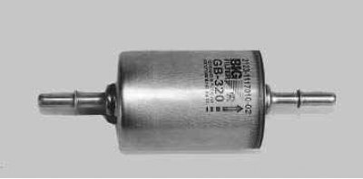
Fuel filter 2 (see fig. 5.19) fine cleaning - full-flow, fixed in bracket 3 on the base of the body next to the fuel tank. The filter is non-separable, equipped with a steel housing with a paper filter element.
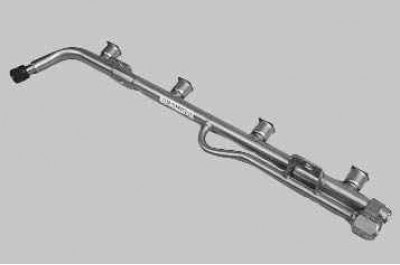
fuel rail 21 (see fig. 5.19), which is a hollow tubular part, serves to supply fuel to the injectors and is fixed on the cylinder head. The engine uses a drainless power supply system, the pressure in the rail is maintained by a fuel pressure regulator installed in the electric fuel pump module. Nozzles 20 are attached to the ramp with clamps 4 (see fig. 5.20) through rubber seals. To equalize the pressure in the injectors, fuel is supplied to the middle part of the rail.
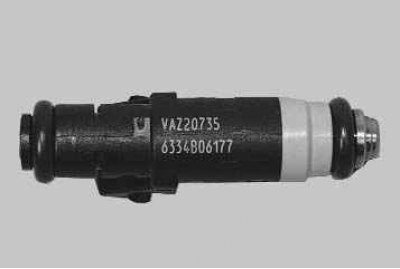
nozzles with their nozzles enter the holes located above the inlet channels of the cylinder head. The nozzles are sealed with rubber O-rings in the holes. The nozzle is designed for metered injection of fuel into the engine cylinders and is a high-precision electromechanical valve in which the shut-off valve needle is pressed against the seat by a spring. When an electrical impulse is applied from the control unit to the electromagnet winding, the needle rises and opens the atomizer hole through which fuel is supplied to the engine intake pipe. The amount of fuel injected by the injector depends on the duration of the electrical impulse.
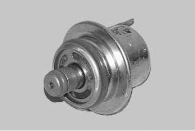
Fuel pressure control installed in the fuel pump module and designed to maintain constant fuel pressure in the fuel rail. The regulator is connected to the beginning of the supply line immediately after the fuel filter and is a bypass valve with a spring having a strictly calibrated force.
Air filter 3 (see fig. 5.21) mounted in front of the engine compartment on three rubber mounts. The filter element is paper, flat, with a large area of the filtering surface. The filter is connected by a rubber corrugated air supply sleeve 11 to the throttle assembly 4. A mass air flow sensor 1 is installed between the sleeve and the filter (see «Electronic engine management system (ECM)»).
Throttle assembly 4 (see fig. 5.21) mounted on the intake manifold 5. It doses the amount of air entering the intake pipe. The intake of air into the engine is controlled by a throttle valve connected to the accelerator pedal drive.
The throttle assembly includes 4 sensors (pic. 5.23) throttle position and idle speed control 5. In the flow part of the throttle assembly (in front of and behind the throttle) there are vacuum extraction holes necessary for the operation of crankcase ventilation systems and trapping fuel vapors.
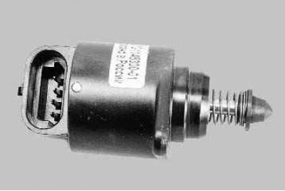
Idling regulator 5 (see fig. 5.23) regulates the idle speed of the crankshaft, controlling the amount of air supplied bypassing the closed throttle. It consists of a two-pole stepper motor and a cone valve connected to it. The valve extends or retracts according to the signals from the engine control unit.
When the regulator needle is fully extended (which corresponds to 0 steps), the valve completely blocks the air passage. When the needle is retracted, an air flow is provided that is proportional to the number of steps the needle moves away from the seat.
By changing the opening and closing of the regulator valve, the control unit compensates for a significant increase or decrease in the amount of air supplied, caused by its suction through a leaky intake system or, conversely, by a clogged air filter.
Evaporative Emission System prevents the release of fuel vapors from the power supply system into the atmosphere, which adversely affect the environment.
The system uses the method of vapor absorption by carbon adsorber 15 (see fig. 5.22). It is installed in the engine compartment on the radiator lining panel and is connected by steam lines to the fuel vapor separator 11 installed in the niche of the left rear wheel, and to the adsorber purge valve 5 located in the engine compartment on the decorative engine cover. The adsorber purge solenoid valve, according to the signals from the engine control unit, switches the operating modes of the system.
Fuel vapors from the tank partially condense into separator 11, the condensate is drained back into the tank through pipe 7. The remaining vapors pass through the gravitational valve 10 installed in the separator through the steam lines 12, 13, 14, 1 and enter the adsorber 15. The second fitting of the adsorber is connected by a hose to the adsorber purge valve 5, and the third - with the atmosphere. When the engine is off, the third fitting is blocked by a built-in non-return valve; in this case, the adsorber is not in communication with the atmosphere. When the engine is started, the ECU begins to supply control pulses to the solenoid valve. The solenoid valve opens, under the action of vacuum, the check valve in the adsorber also opens, due to this, air from the atmosphere and fuel vapor from the separator enter the adsorber. At this time, the sorbent is purged: gasoline vapors are discharged through hoses 4 and throttle assembly 4 (see fig. 5.21) into intake manifold 5.
Malfunctions of the evaporative emission system entail idle instability, engine shutdown, increased toxicity of exhaust gases and deterioration in driving performance of the vehicle.