



- bore gauge;
- soft metal rod (∅ 21 mm).
Disassembly
1. Remove the piston rings from the piston (see above).
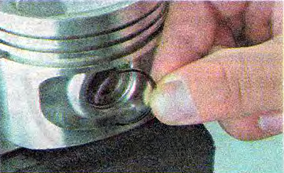
2. Using an awl, pry up and remove the piston pin retaining rings from the grooves.
3. Using a soft metal rod of suitable diameter, push out the piston pin.
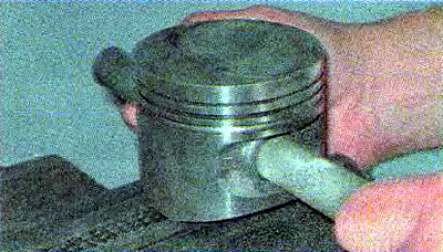
4. Remove the piston from the connecting rod.
Selection of pistons for block cylinders
In new engines, the clearance between the piston and the cylinder is 0.025-0.045 mm and is set by installing pistons of the same class as the cylinder class.
1. Using a bore gauge, check the wear of the cylinder walls (see "Piston and connecting rod - replacement").
Cylinder diameters are divided into five size classes (see table 16.4). The class of each cylinder is stamped on the lower mating surface of the cylinder block.
Table 16.4. Cylinder classes by diameter
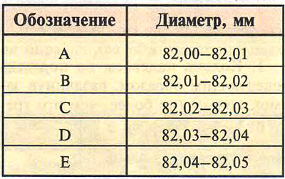
Recommendation. Slight uniform wear of the cylinder (within 0.05 mm) it is possible to compensate by installing a piston of a different class with a larger diameter.
If the maximum wear is 0.15 mm or more, the cylinders must be bored and pistons of a repair size must be installed.
It is possible to bore cylinders by 0.4 mm and 0.8 mm to suit the dimensions of repair pistons.
2. The designations on the piston bottom indicate where:
- 2 - piston pin hole class;
- C - piston class;
- "left arrow" - arrow for orienting the piston in the cylinder (should be directed towards the timing drive);
- G - piston mass group.
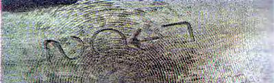
According to the diameter of the hole for the piston pin, pistons are divided into three classes (1, 2, 3) - by 0.004 mm.
According to the outer diameter, pistons are divided into five classes (A, B, C, D, E) — through 0.01 mm (measured in a plane perpendicular to the piston pin, at a distance of 55 mm from the piston bottom).
According to size, pistons are divided into nominal and two repair sizes. Pistons are not marked with nominal size. Pistons of the first repair size are manufactured with a diameter increased by 0.4 mm and are marked with the symbol "□". Pistons of the second repair size have a diameter increased by 0.8 mm and are marked with the symbol "□".
All pistons in an engine must be of the same weight group. Pistons of the nominal group are designated by the symbol "G". Pistons with increased and decreased mass by 5 g are designated "+" and "-" respectively.
The finger class is marked with paint on its end.
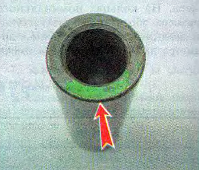
Note: The connecting rod and piston group can be equipped with either pins 2108-1004020 with increased wall thickness, or pins 2110-1004020.
Table 16.5. Connecting rod classes by weight
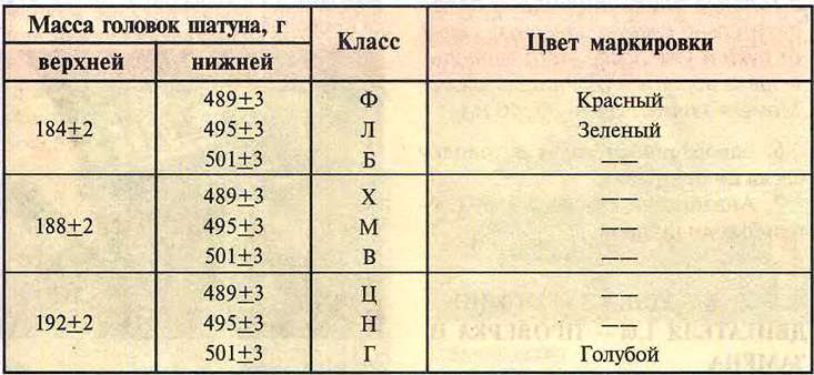
Table 16.6. Piston pin classes by outside diameter and pin hole diameter
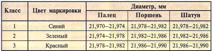
According to the outer diameter, the fingers are divided into three classes (blue, green and red), through 0.004 mm.
To facilitate the selection of the pin for the piston hole, the required pin class is indicated on its inner side with paint.
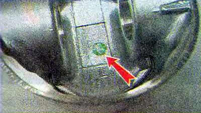
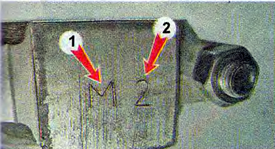
The required pin class is indicated on the connecting rod cap 2. Connecting rods are divided into classes according to the weight of the heads. Marking is applied to the connecting rod cover 1...
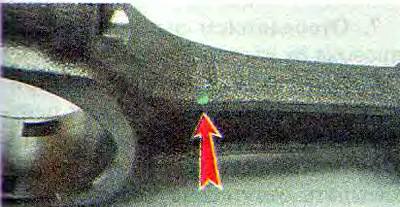
...or paint.
Warning! The engine must be equipped with connecting rods of the same weight class (see table 16.5).
Assembly
We assemble the piston with the connecting rod in the reverse order of disassembly.
Warning: When assembling the connecting rod with the piston, make sure that the marking on the connecting rod and the marking on the piston are facing the same way.
When installing the piston into the cylinder, the connecting rod with the cylinder number should face the side of the block on which the lug for installing the oil filter is located, and the catalog number should face the front end of the crankshaft.