



Engine cylinder block cast from special high-strength cast iron, which gives the engine structure rigidity and strength.
The coolant passages that form the cooling jacket are made along the entire height of the block, which improves piston cooling and reduces block deformation from uneven overheating. The cooling jacket is open at the top towards the engine block head. At the bottom of the cylinder block there are five crankshaft main bearing supports, the covers of which are attached with bolts. The supports contain thin-walled steel-aluminum liners that act as crankshaft bearings. The middle support has grooves into which thrust half rings are inserted, holding the crankshaft from axial movements.
Compared to the engine block mod. 2111 cylinder block mod. 21114 is 2.3 mm higher, the height from the axis of the main bearing beds to the upper plane of the block is 197.1 mm.
Crankshaft cast from special high-strength cast iron. The main and connecting rod journals of the crankshaft are ground. To lubricate the connecting rod bearings, oil channels are drilled in the crankshaft and closed with plugs. Eight counterweights located on the crankshaft serve to reduce vibration. Crankshaft radius of engine mod. 21114 is 2.3 mm larger than the engine mod. 2111, due to this the piston stroke increased from 71 to 75.6 mm. To distinguish the shafts on one of the counterweights of the crankshaft of the engine mod. 21114 the marking "1118" is cast.
An oil pump, a toothed pulley for the camshaft drive belt and a generator drive pulley with a built-in torsional vibration damper are mounted on the front end of the crankshaft. At the rear end of the crankshaft is a flywheel, cast from cast iron. A steel toothed rim is pressed onto the flywheel.
Connecting rods steel, forged, with covers on the lower heads. Thin-walled liners are installed in the lower head of the connecting rod, and a steel-bronze bushing is pressed into the upper head.
Pistons cast from aluminum alloy. Each of them has three rings: two upper compression rings and a lower oil scraper ring. The piston bottoms have a recess for the combustion chamber and two recesses for the valves.
Oil pan steel, stamped, bolted to the cylinder block from below.
Cylinder head, installed on top of the cylinder block, is cast from aluminum alloy. The lower part of the cylinder head contains cast channels through which the liquid that cools the combustion chambers circulates. The camshaft is installed in the upper part of the cylinder head. The camshaft rotates in supports made in the upper part of the cylinder head and in two bearing housings secured with nuts on studs screwed into the cylinder head.
Combustion chamber in the engine block head mod. 21114 has become larger compared to the engine mod. 2111: its length increased from 79 to 81 mm, and its width from 48 to 50 mm. To distinguish the cylinder heads, next to the threaded hole for the spark plug of the 1st cylinder of the engine head mod. 21114 is a tide with the number "1118".
Camshaft the car is cast from cast iron. To reduce wear, the working surfaces of the cams and the surface under the oil seal are heat-treated - bleached.
Due to the fact that the engine mod. 21114 uses phased fuel injection, a phase sensor is installed in the engine management system. To ensure its operation, a marker pin is pressed into the rear journal of the camshaft.
The camshaft cams operate the valves through the tappets. Steel adjusting washers are installed in the upper part of the pushers, the selection of which regulates the clearances in the valve drive.
The engine has two valves per cylinder: one intake valve and one exhaust valve.
The valve guides and seats are pressed into the cylinder head. The guide bushings are also equipped with retaining rings to prevent them from falling out. The guide bushings are fitted with oil scraper caps to reduce oil ingress into the cylinders.
There are two springs on each valve. The camshaft is driven by a rubber toothed belt from the crankshaft. Camshaft pulleys for engines mod. 21114 and 2111 differ: mark for setting the valve timing on the engine pulley mod. 2111 is located in the middle of the cavity between the teeth, and in the engine mod. 21114 is shifted by 2°.
Engine lubrication system on a car, combined: spraying and under pressure. Main and connecting rod bearings and camshaft supports are lubricated under pressure. The engine lubrication system consists of an oil sump, a gear oil pump with an oil receiver, a full-flow oil filter, an oil pressure sensor and oil channels.
Engine cooling system consists of a cooling jacket, a radiator with an electric fan, a centrifugal water pump, a thermostat, an expansion tank and hoses.
Engine power supply system includes an electric fuel pump installed in the fuel tank, a throttle assembly, a fine fuel filter, a fuel pressure regulator, injectors and fuel hoses. Differences between the elements of the engine power supply system mod. 21114 from engine mod. 2111:
- tubular fuel rail without backflow is made of stainless steel instead of aluminum;
- reduced size fuel injectors are not interchangeable with previous injectors;
- the redesigned fuel pressure regulator is installed in the fuel pump module rather than on the fuel rail;
- the throttle assembly does not have a hole connecting the air supply hose to the intake module bypassing the throttle valve. The throttle body flange configuration has been changed.
The engine power supply system functionally includes fuel vapor recovery system with a carbon adsorber (see "Replacing the fuel vapor recovery system components"), which prevents fuel vapors from escaping into the atmosphere.
Ignition system consists of an ignition coil mounted on a special bracket on the cylinder block, spark plugs and high-voltage wires. The ignition coil is controlled by the engine electronic control unit (ECU). Installing an ignition coil controlled by the ECU instead of the engine ignition module mod. 2111, increased system reliability.
Engine crankcase ventilation system closed, with crankcase gases discharged through mesh 7 (figure 4.3) oil separator installed in the cover 6 of the cylinder head, into the intake pipe. The crankcase gases are then directed into the engine cylinders, where they are burned. When the engine is idling, crankcase gases enter through hose 3 of the small circuit through a calibrated hole (jet) in the throttle body. In this mode, a high vacuum is created in the intake manifold and crankcase gases are effectively sucked into the throttle body space. The jet limits the volume of gases sucked out so that the engine operation at idle speed is not disrupted. When the engine is running under load, when the throttle valve is partially or fully open, the main volume of gases passes through hose 5 of the large circuit into the air supply sleeve 4 in front of the throttle assembly and then into the intake pipe and combustion chambers.
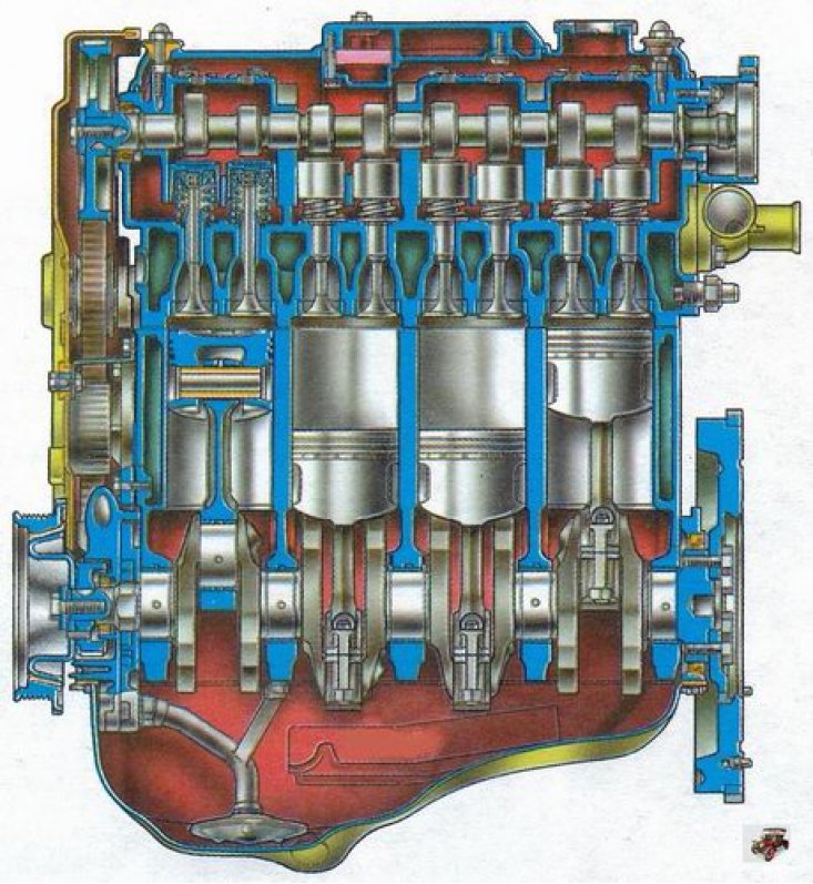
Figure 4.1. Longitudinal section of the engine
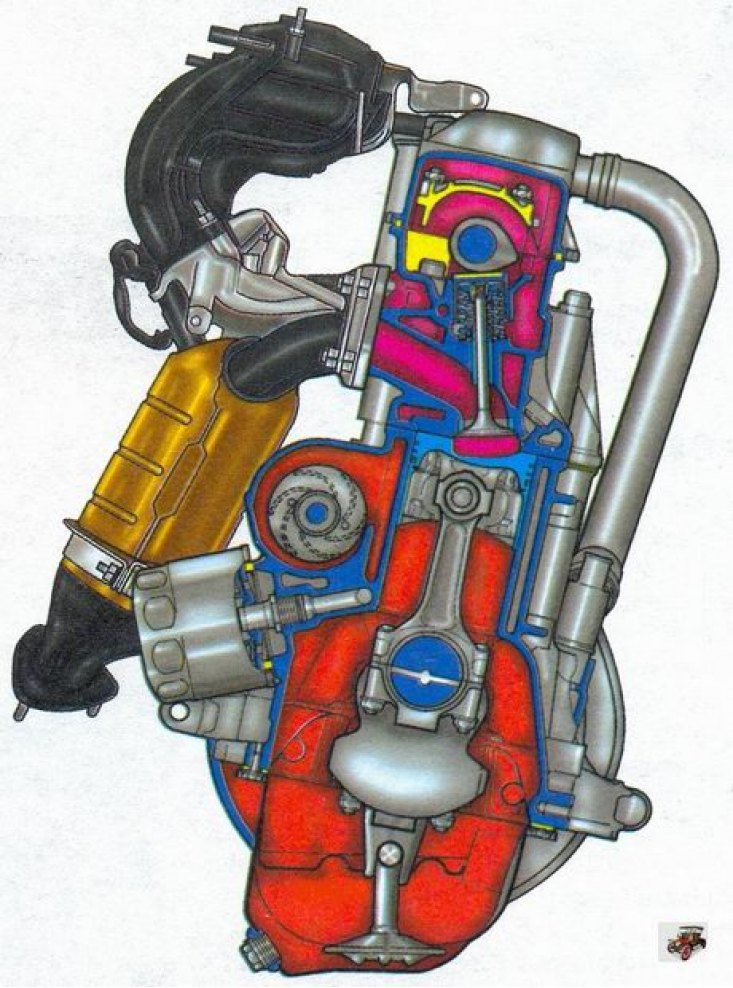
Figure 4.2. Cross-section of the engine
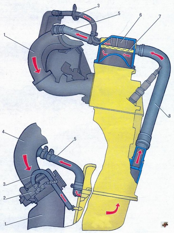
Figure 4.3. Diagram of the engine crankcase ventilation system: 1 - intake module; 2 - throttle assembly; 3 - small circuit ventilation system hose; 4 - air supply hose; 5 - large circuit ventilation system hose; 6 - cylinder head cover; 7 - oil separator mesh; 8 - exhaust hose