



The cylinder block is cast iron, with cylinders machined into it. The internal cavities of the block for the coolant are formed during its casting, and the oil supply channels are made by drilling. At the bottom of the cylinder block there are five crankshaft main bearing supports. The main bearing caps are not interchangeable and are marked with the bearing serial number, starting from the crankshaft pulley. In the cover of the second main bearing there are two threaded holes for the oil intake mounting bolts. Steel-aluminum main bearing shells are installed in the supports and covers. On both sides of the support of the third main bearing there are sockets for installing thrust half rings that prevent axial movement of the crankshaft. The front half-ring is made of steel-aluminum, the rear half-ring is made of metal-ceramic, yellow on both sides.
Engines 11194 and 21126 differ from previous models in their lightweight connecting rod and piston group.
Short skirt pistons, cast from aluminum alloy. Four small recesses for valve plates are made in the bottom of each piston, but they do not prevent the valve from contacting the piston in case of a timing failure or a timing belt break. Each piston has two compression rings and one oil scraper ring. The lower compression ring is of the scraper type with a groove and a sharp edge on the lower plane. A spring expander is installed inside the oil scraper ring. All rings are thinner than on previous engine models, which is designed to reduce internal engine friction losses.
The pins are of the floating type and are fixed in the pistons by two spring retaining rings.
The connecting rods are "split"**. A steel-bronze bushing is pressed into the upper head of the connecting rod. The connecting rod caps are not interchangeable and are installed on the connecting rod in only one position.
The oil pan is attached to the cylinder block from below.
The engine lubrication system is combined - under pressure and by splashing. The oil pump is a gear type with internal engagement and is driven from the front end of the crankshaft. Through the oil intake, the pump takes oil from the oil pan and forces it under pressure into the channels of the engine lubrication system. To control the amount of oil in the pan, a dipstick is installed - a level indicator. The oil filter is full-flow, with a paper filter element and a check valve that prevents oil from leaking from the lubrication system channels into the oil pan after the engine has stopped.
* Features of the design, maintenance and repair of the 8-valve engine are described in the chapter "Features of the design and repair of modifications of the LADA KALINA car" (see p. 207).
** The connecting rod and its cover are first manufactured as a single unit (non-detachable) detail. After making holes in the upper and lower heads of the connecting rod, the lower head is "split" using a special method. This technology allows for a perfect connection between the cover and the connecting rod.
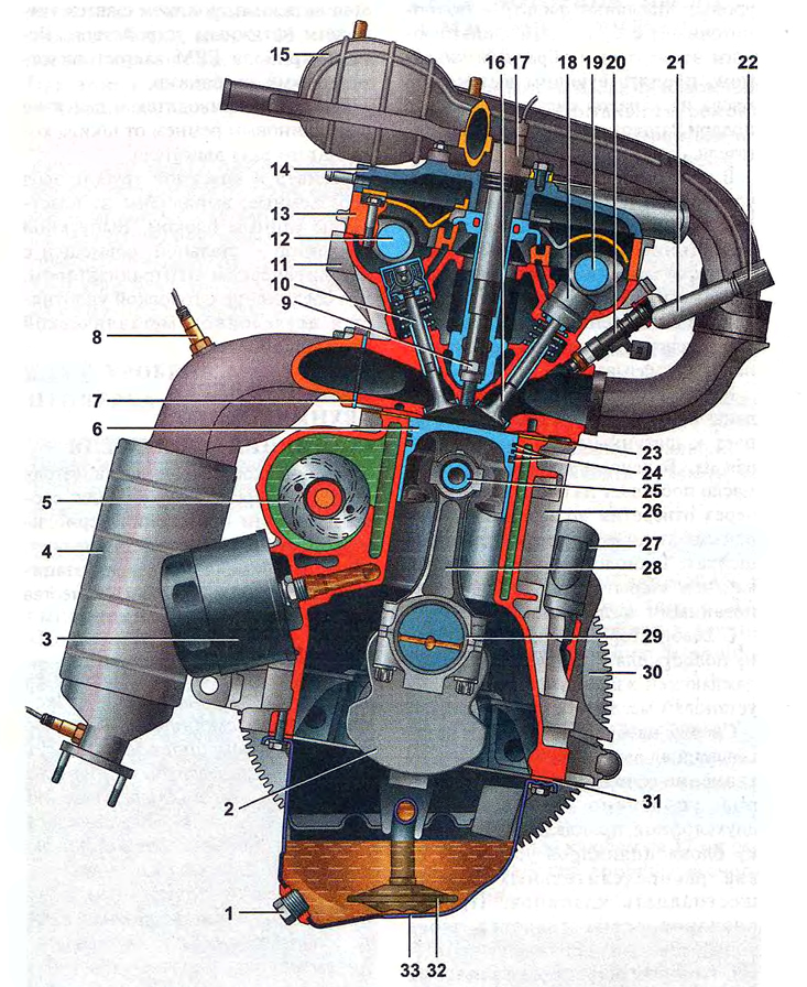
Cross section of a 16-valve engine*:
1 - oil pan drain plug;
2 - crankshaft;
3 - oil filter;
4 - catalytic collector;
5 - coolant pump;
6 - piston;
7 - catalytic collector gasket;
8 - oxygen concentration sensor;
9 - spark plug;
10 - exhaust valve;
11 - cylinder head;
12 - exhaust camshaft;
13 - camshaft bearing housing;
14 - cylinder head cover;
15 - intake module;
16 - inlet valve;
17 - ignition coil;
18 - hydraulic pusher;
19 - intake camshaft;
20 - nozzle;
22 - fuel rail diagnostic connector;
21 - fuel rail;
23 - cylinder head gasket;
24 - piston rings;
25 - piston pin;
26 - cylinder block;
27 - crankcase ventilation system nipple;
28 - connecting rod;
29 - connecting rod bearings;
30 - flywheel;
31 - Oil pan gasket;
32 - oil intake;
33 - engine oil pan.
Oil nozzles are installed in the main bearing supports. Oil from the nozzles is supplied to the inner surfaces of the pistons to cool them. Some of the oil gets onto the upper heads of the connecting rods and flows through the conical holes made in them onto the piston pins, lubricating them.
Channels are drilled in the body of the crankshaft. Through them, oil flows to the connecting rod journals, lubricating them. Oil enters the crankshaft channels from the cylinder block through openings in the main bearing shells and main journals. The technological openings of the channels are closed with stamped steel plugs.
On the left side of the block there is a cavity for installing the coolant pump and a lug for installing the oil filter.
An aluminum head is installed on top of the cylinder block. The connection between the head and the cylinder block is sealed with a two-layer metal gasket. The cylinder head contains two camshafts and sixteen valves. The valves are driven by pushers with hydraulic compensators. Therefore, adjustment of thermal clearances in the valve drive is not required. The intake and exhaust camshafts are not interchangeable. The camshaft supports are made in the head, and their covers are combined into a bearing housing installed on the head. The bearing housing is covered from above by a cylinder head cover with an oil deflector and an oil filler neck. To install spark plugs, cylindrical recesses called spark plug wells are made on top of the cylinder head. An ignition coil is inserted into each well, with the high-voltage terminal of the coil placed on the spark plug.
The camshafts and coolant pump are driven by a toothed belt from the engine crankshaft. To guide the movement of the belt along the pulleys, a guide roller is installed; the belt is tensioned by a tension roller with an automatic tensioner. The timing belt is covered with plastic covers.
The generator is driven by a poly-V belt from the engine crankshaft pulley.
The receiver and intake manifold are non-detachable and made of plastic as a single unit. The exhaust manifold is steel and is combined with a catalytic converter. Its connection with the head is sealed with a two-layer metal gasket.