



The main element of the front suspension is a hydraulic telescopic shock absorber strut 8 (figure 6.1), the lower part of which is connected to the steering knuckle 13 by two bolts 11 and 12. The upper bolt 11, passing through the oval hole of the rack bracket, has an eccentric belt and an eccentric washer. Turning the top bolt changes the camber of the front wheel.
A coiled conical spring 6, a polyurethane foam buffer 22 of the compression stroke and an upper support 3 of the strut assembled with a bearing 4 are installed on the telescopic strut. The upper support is secured with three self-locking nuts to the strut of the body mudguard. Due to its elasticity, the support ensures the "swinging" of the rack during suspension movements and dampens high-frequency vibrations. The bearing built into it allows the stand to rotate together with the steered wheels. The parts of the hydraulic telescopic shock absorber are mounted in the housing of the rack.
The lower part of the steering knuckle is connected by a ball joint 18 to the lower arm 17 of the suspension. The braking and traction forces are perceived by longitudinal stretchers 16, which are connected through silent blocks to the lower arms and front supports of the front suspension crossmember. Adjusting washers are installed at the junctions of the tension rod with the lever and the front support, which regulate the longitudinal tilt angle of the pivot axis. A double-row closed-type radial thrust bearing is mounted in the steering knuckle 13, on the inner rings of which the wheel hub 19 is installed with tension. The bearing is tightened with a nut 20 on the tailpiece of the outer joint housing of the wheel drive and is not adjustable. All front and rear wheel hub mounting nuts are identical and have right-hand threads.
The anti-roll bar is a rod 15, the knees of which are connected to the lower arms 17 of the suspension through struts with rubber hinges and silent blocks. Average (torsion) part of the rod is attached to the body with brackets through rubber cushions.
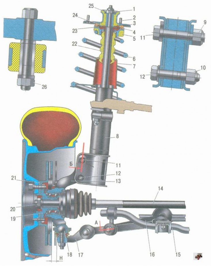
Figure 6.1. Front suspension assembly of the vehicle: 1 - nut for fastening the upper support of the rack; 2 - bolt; 3 - upper support of the front suspension strut; 4 - upper support bearing of the rack; 5 - upper spring insulating gasket; 6 - front suspension spring; 7 - protective cover; 8 - telescopic stand assembly; 9, 10 - nuts for fastening the strut to the steering knuckle; 11 - bolt with eccentric; 12 - bolt; 13 - steering knuckle; 14 - front wheel drive shaft; 15 - stabilizer bar; 16 - stretching; 17 - lever; 18 - ball joint; 19 - hub; 20 - hub mounting nut; 21 - brake disc; 22 - front suspension compression buffer; 23 - upper spring cup; 24 - upper strut support compression stroke limiter; 25 - upper support travel limiter; 26 - stabilizer bar mounting nut; H - control size