



1. Remove the starter from the vehicle (see "Removal and installation the starter").
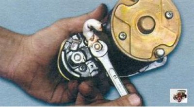
2. Loosen the nut securing the tire to the starter contact bolt.
3. Disconnect the busbar from the contact bolt of the starter solenoid relay.
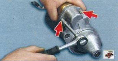
4. Unscrew the two bolts securing the starter traction relay and remove the relay.
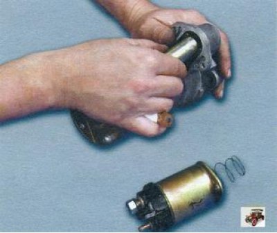
5. Remove the traction relay anchor by lifting it upwards so that the anchor loop is removed from the lever.
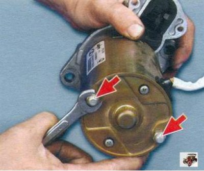
6. Unscrew the two nuts of the tie rods.
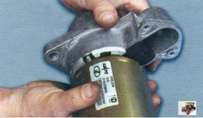
7. Remove the starter cover from the drive side with the gearbox and drive assembly.
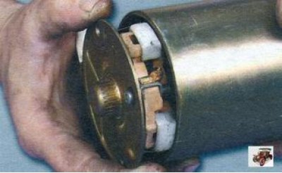
8. Remove the starter cover from the collector side with the brush holder and brushes.
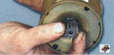
9. Remove the starter gear from the armature shaft.
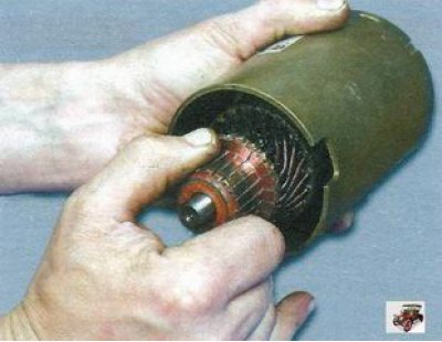
10. Remove the anchor from the stator.
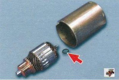
11. Please note that a washer is installed on the starter armature shaft on the drive side.
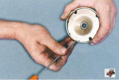
12. Remove the starter armature shaft support.
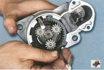
13. Remove the two tie rods from the starter cover on the drive side. It is not necessary to unscrew these studs, but it is more convenient to remove the gearbox and drive without them.
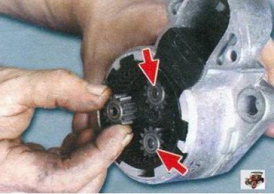
14. Remove the three planetary gears from the gearbox. If their teeth or needle bearings embedded in the gears are damaged, replace the gears.
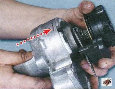
15. Remove the gearbox with the drive from the cover by pressing on the starter drive gear.
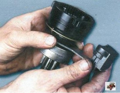
16. Remove the support with the seal from the lever.
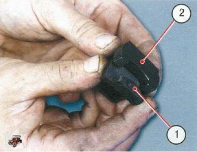
17. Remove support 1 from seal 2. The plastic support should not be significantly worn or damaged. Replace a defective support, as well as a heavily deformed or hardened rubber sealing gasket.
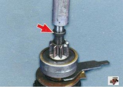
18. Knock the stop ring off the retaining ring using a suitable drift.
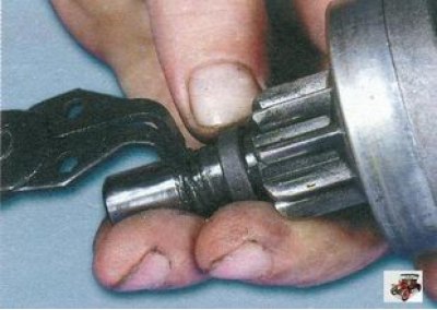
19. Remove the retaining ring and then the limiting ring.
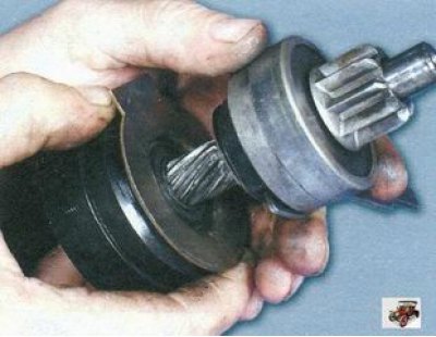
20. Remove the drive assembly from the drive shaft.
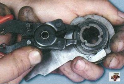
21. Remove the lever retaining ring.
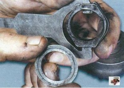
22. Remove the lever with the leash and washer.
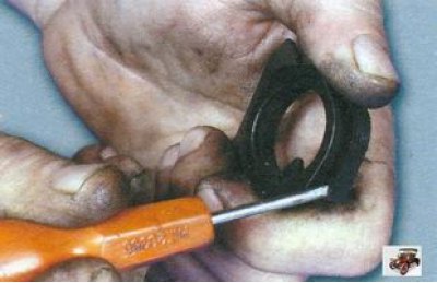
23. Remove the lever spring.
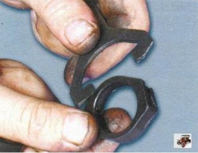
24. Remove the lever from the leash and separate the halves of the lever.
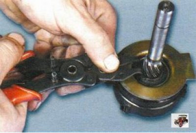
25. Remove the internal gear retaining ring.
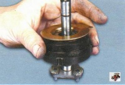
26. Remove the internal gear and drive shaft support from the shaft.
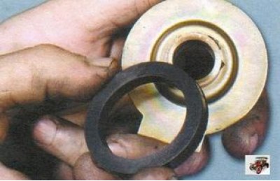
27. Remove the sealing ring from the support. Replace a ring that is severely deformed or has lost elasticity.
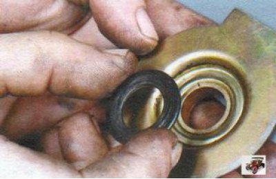
28. Remove the insert from the support.
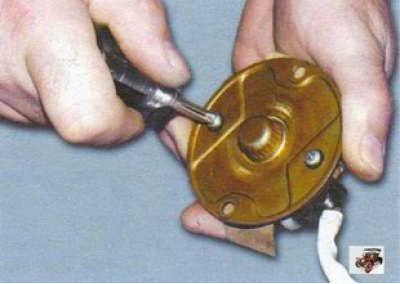
29. Loosen the two screws and remove the brush holder from the cover on the collector side.
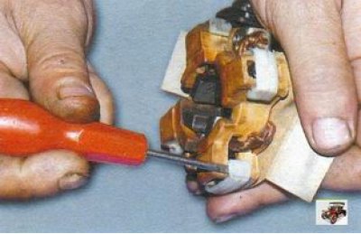
30. Using a screwdriver, pry up the brush holders...
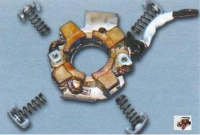
31. ...remove them and the pressure springs. Replace deformed or damaged retainers and heavily compressed or bent springs.
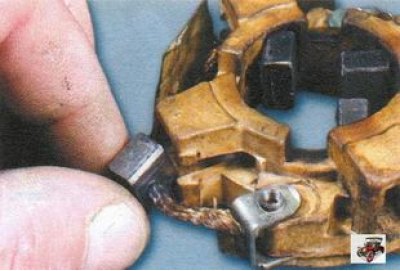
32. Remove the starter brushes from the brush holder guides.
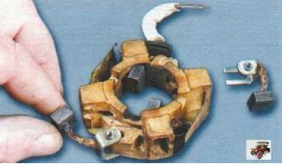
33. Remove the non-insulated brushes.
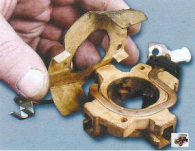
34. Remove the cardboard insulation pad. Replace a torn or excessively compressed gasket.
35. Remove the connecting busbar with insulated brushes.
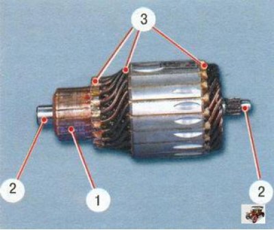
36. Inspect the starter armature. If collector 1 is dirty or has scratches, burn marks, etc., sand the collector with fine glass sandpaper. If you find yellow deposits from the bearing on shaft 2 of the starter anchor, remove them with fine sandpaper, as this may cause the gear on the shaft to jam. Check the reliability of the soldering of the terminals of the 3rd armature winding to the collector plates. Inspect the starter winding at the ends of the anchor; the winding diameter should be smaller than the anchor iron package. Otherwise, replace the starter anchor.
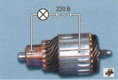
37. Check the condition of the starter armature winding using a test lamp powered by 220 V alternating current. Apply voltage to the collector plate and the starter armature core. The lamp should not burn. If the lamp lights, it means that there is a short circuit in the starter armature winding or the collector plate to ground. In this case, replace the starter armature.
38. While holding the overrunning clutch, turn the starter gear in both directions: the starter gear should rotate freely clockwise, but should not rotate counterclockwise. Otherwise, replace the starter drive.
39. Install the starter drive on the drive shaft; it should move freely along the shaft splines without jamming.
40. If the starter drive components are badly worn or damaged, replace the starter drive. If you find nicks on the leading edge of the gear teeth, grind them with a small diameter fine-grained emery wheel.
41. Inspect the bushings in which the shafts rotate, installed in the starter drive side cover, the commutator side cover, the armature shaft support and the starter drive shaft support. If the bushings are worn or have burrs, pits or other defects, replace the starter covers or supports with defective bushings. Also replace starter covers and supports if they are cracked.
42. Inspect the starter stator; if there are signs of anchor contact, replace the rear starter cover and intermediate support.
43. Replace starter brushes that are worn to a size between the working surface and the terminal of less than 3.5 mm.
44. Check the ease of movement of the starter brushes in the brush holder guides. They should move without jamming, and the brush holder itself should not have chips or cracks.
45. Inspect the starter drive shaft. The screw splines and necks must not have any scoring or severe wear. Remove traces of copper transfer from the bushings on the journals with fine glass sandpaper, as they may subsequently cause the shaft to jam. The planet carrier and its three gear axes must not have any play in the connections.
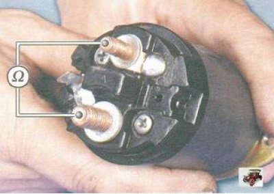
46. Use an ohmmeter to check whether the contact plate closes the contact bolts of the starter traction relay. To check, assemble the circuit shown in the photo and push the starter armature into the traction relay until it stops. If the bolts do not close, replace or repair the starter solenoid.
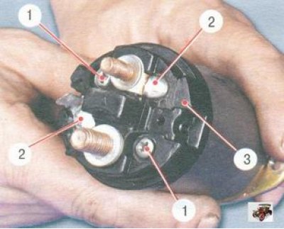
47. To repair the starter traction relay, unscrew the two screws 1 and unsolder the terminals 2 of the traction relay windings, remove the cover 3, clean the bolt heads and the contact plate with emery paper. If the bolt heads are badly burnt, rotate the bolts 180°. Assemble the starter solenoid in the reverse order
48. Assemble the starter in reverse order. Before assembling the starter, lubricate the drive gear teeth with engine oil, the drive shaft helical splines, internal gear teeth, planetary gears and rotor shaft splines with consistent grease (CIATIM-201, 202, 203 or Litol-24).
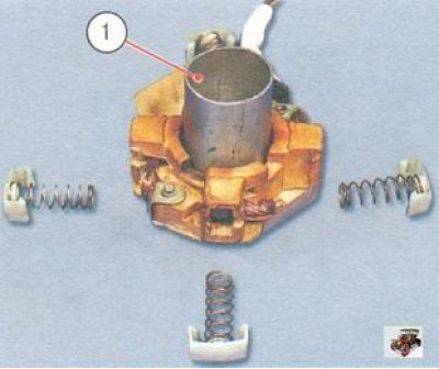
49. The brush holder must be installed in the starter separately from the cover on the collector side, since the starter brushes are pushed out of the guides by springs and it is impossible to hold them in their original position without a special device. For preliminary assembly and installation of the brush holder, use a thin-walled mounting sleeve 1 with a diameter equal to or slightly larger than the diameter of the collector (about 30 mm).
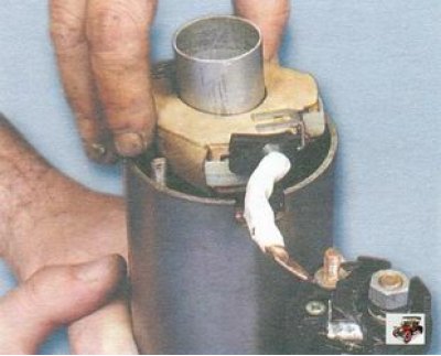
50. Install the assembled brush holder into the starter housing until it stops, remove the mounting sleeve and install the cover from the collector side.