



The clutch consists of a basket (pressure plate assembly) and the driven disk. The basket is a steel casing in which a pressure spring and a pressure disk are installed. The pressure plate is secured in the casing by three pairs of elastic plates. From the casing side, the disk is pressed by a diaphragm-type pressure spring. The clutch basket is attached to the flywheel with six bolts and is covered by an aluminum housing. A driven disk is installed between the pressure plate and the flywheel.
Friction linings are riveted to both sides of the driven disk. To dampen torsional vibrations at the moment the clutch is engaged, a damper with six cylindrical springs is built into the driven disk. The driven disk hub engages splined with the primary shaft of the gearbox.
The clutch pedal is suspended on an axle and attached to the body via a bracket. The upper part of the clutch pedal is designed as a double-arm lever. At the end of the lever there is a pin to which the clutch release cable is connected. The connection is made through a special ratchet mechanism that regulates the length of the cable (see below). Therefore, during the operation of the car, there is no need to regularly check and adjust the working stroke of the clutch pedal. This mechanism also ensures that there is no play in the clutch release drive.
The cable is laid in a metal sheath with a polyethylene coating. The upper end of the shell has a bracket with which it is attached to the pedal assembly. The vertical surface of the bracket also serves as a limiter for the clutch pedal travel. A rubber plate is installed on it. The lower end of the cable sheath is secured in a bracket mounted on the gearbox housing. The lower end of the cable is covered with a rubber corrugated cover. The cable is connected to the clutch release fork lever via a plastic leash screwed onto the threaded end of the cable.
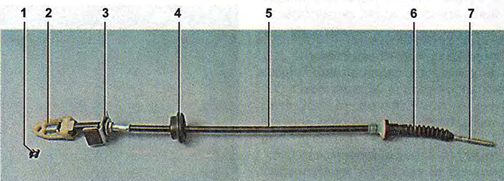
Clutch release cable:
1 - spring retaining bracket;
2 - automatic cable length adjustment mechanism;
3 - cable sheath bracket;
4 - rubber cover;
5 - cable sheath;
6 - corrugated cover of the lower end of the cable;
7 - threaded (lower) end of the cable.
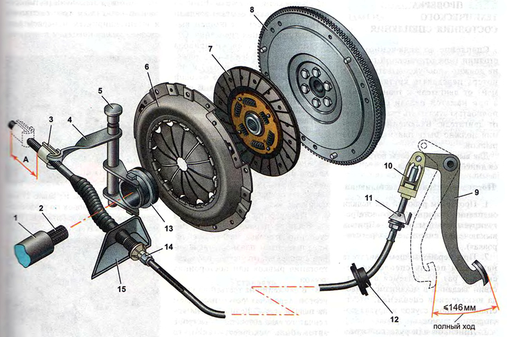
Clutch:
1 - release bearing guide sleeve;
2 - primary shaft of the gearbox;
3 - cable leash;
4 - clutch release fork;
5 - fork axle bushing;
6 - pressure plate assembly (basket);
7 - slave disk;
8 - flywheel;
9 - clutch pedal;
10 - automatic cable length adjustment mechanism;
13 - Clutch release sleeve (release bearing);
15 - bracket mounted on the gearbox housing;
14 - lower end of the cable sheath;
A - the distance of the leash displacement, checked when installing the cable (27 mm).
The clutch release fork is twisted in two bushings. The upper bushing is plastic and removable, while the lower one is bronze and pressed into the clutch housing. When the fork is turned, the force is transmitted to the petals of the pressure spring through a radial thrust ball bearing (release bearing). The bearing is mounted on the clutch release sleeve, through which it contacts the fork of the drive release of the fastening. A U-shaped spring ensures constant engagement of the fork and clutch. Due to the absence of a gap in the clutch release drive, constant pressure of the clutch against the petals of the pressure spring is ensured, while the release bearing operates continuously. The bearing is lubricated for its entire service life. The clutch release sleeve moves along a guide sleeve mounted on the primary shaft of the gearbox and attached to the clutch housing with three bolts.
During operation, the driven disk linings wear out. To compensate for this wear, a mechanism for automatic cable length adjustment is built into the clutch release drive. As the linings wear out, the clutch release fork lever rotates, pulling the cable. At the same time, the spring located in the sleeve of the adjustment mechanism is compressed and presses the locks of the toothed end of the cable. The clamps release the tip, allowing it to pull freely from the cable guide, compensating for wear on the disc linings. When the clutch pedal is pressed, the upper lever moves upward. At the same time, the clamps compress the toothed end of the cable, preventing it from sliding out of the housing of the adjustment mechanism.
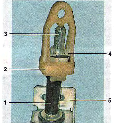
Cable length adjustment mechanism:
1 - bushing;
2 - leash;
3 - toothed (upper) end of the cable;
4 - cable end clamps;
5 - bracket (with clutch pedal travel limiter).
Note: On early production vehicles, a spring was installed inside the leash.