



To flush the throttle assembly, you will need a product to clean the engine intake manifold. As a last resort, you can use a carburetor cleaner. If the cleaner fails to eliminate the malfunction, the throttle assembly must be replaced. After removing the throttle assembly, the gasket (sealing ring) needs to be replaced. You may need a product to clean and protect electrical contacts.
To perform the test you will need a multimeter.
Note: When installing a new throttle assembly on a vehicle, special diagnostic equipment may be required to check the "calibration" of the throttle position at extreme positions. This operation can be performed at a specialized service station.
For ease of work, you can remove the air intake system muffler (see "Air filter - removal and installation").
Sequence of execution
1. Prepare the car for work and disconnect the wire terminal from the negative terminal of the battery (see "Preparing the car for maintenance and repair").
2. Remove the decorative engine cover (see "Engine trim panel - removal and installation"),
3. Using an 8 mm socket wrench or a Phillips screwdriver, loosen the clamp securing the hose to the throttle body pipe.
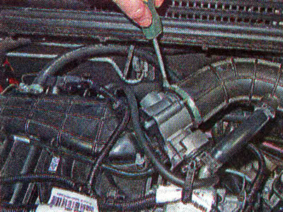
4. Using the same key or screwdriver, loosen the second clamp securing the hose to the air filter pipe.
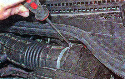
5. Remove the air supply hose to the throttle valve from the pipes and move it to the side.
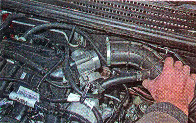
6. Using a slotted screwdriver, pry up the retainer...
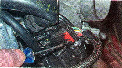
...and disconnect the wiring harness connector from the throttle assembly.
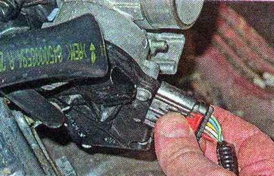
7. Visually check the condition of the throttle assembly terminals and the wiring harness block. To remove oxides, spray the terminals with a cleaning and protection agent for electrical contacts.
8. Using a 13 mm socket wrench, unscrew the three mounting nuts and remove the throttle assembly.
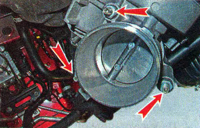
9. Remove the sealing ring from the intake manifold flange.
10. Using a multimeter in ohmmeter mode, measure the resistance of the throttle position sensor between terminals 2 and 3, which should be within 750–1250 Ohms.
Warning! When performing the following operation, hold the throttle assembly with the electric drive upwards so that the cleaning agent cannot flow down the throttle shaft towards the gear motor and get inside the mechanism.
11. Using a cleaning agent, wash away deposits from the inner walls of the throttle assembly and from the throttle valve.
12. Wipe the throttle assembly with a clean cloth and blow it with compressed air from a compressor or foot pump.
13. Install the throttle assembly in the reverse order, replacing the sealing ring with a new one. We apply anaerobic thread lock to the threaded part of the throttle assembly mounting stud. Tighten the nuts to a torque of 6-8 Nm.
Note: After the ignition is turned on, the throttle assembly must perform a full cycle of checking the angles of maximum and minimum throttle opening. To do this, you must wait at least 30 seconds with the ignition on before starting the engine for the first time. When installing a new throttle assembly, it is advisable to check the throttle position reprogramming using special diagnostic equipment. This procedure may be required after replacing the electronic control unit (ECU). It can be performed at a specialized service station with the necessary equipment.
Table 9.2.3. Purpose of the throttle assembly terminals of the 21129 engine
| Output number | Electrical circuit of the throttle assembly | Purpose of the output |
| 1 | Throttle actuator motor-reducer | Motor winding output* |
| 2 | Throttle Position Sensors | Supply voltage |
| 3 | "Weight" | |
| 4 | Throttle actuator motor-reducer | Motor winding output* |
| 5 | Throttle Position Sensors | Signal from sensor #1 |
| 6 | Signal from sensor #2 |
* The polarity of the supply voltage supplied to the electric motor changes depending on which direction the throttle valve needs to be turned.