
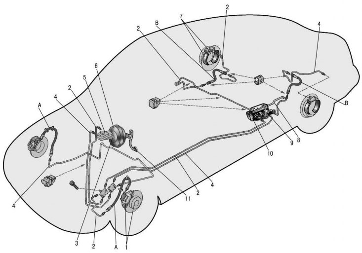
Pic. 9.1. Scheme of the hydraulic drive of the brakes: 1 – the brake mechanism of a forward wheel; 2 – a flexible hose of a forward brake; 3 - pipeline circuit left front - right rear brake; 4 - the main cylinder of the hydraulic drive of the brakes; 5 - pipeline circuit right front - left rear brake; 6 – a tank of the main cylinder; 7 - vacuum amplifier; 8 - brake mechanism of the rear wheel; 9 – a flexible hose of a back brake; 10 - pressure regulator; 11 - brake pedal
The vehicle is equipped with a dual-circuit service brake system with diagonal separation of circuits (pic. 9.1), which greatly improves driving safety. One hydraulic drive circuit ensures the operation of the right front and left rear brake mechanisms, the other - the left front and right rear.
If one of the circuits of the working brake system fails, the second circuit is used, which ensures that the car stops with sufficient efficiency.
The hydraulic drive includes a vacuum booster 7 and a double-circuit regulator 10 of the pressure of the rear brakes.
The parking brake system is driven by the rear wheel brakes.
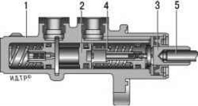
vacuum booster (pic. 9.2) diaphragm type works on the principle of pressure difference in the vacuum and atmospheric chambers, as a result of which, when you press the brake pedal, an additional force is created on the piston of the main brake cylinder. The rubber diaphragm 8, together with the valve body 17, divides the cavity of the vacuum booster into two chambers: vacuum A and atmospheric B. Chamber A is connected to the engine intake manifold through a tip check valve and a hose.
Valve body 17 is plastic. At the exit from the cover, it is sealed with a corrugated protective cover 11. The stem 2 of the main cylinder drive with a support sleeve, piston 10, valve 15 assembly, return springs 13 and 14, respectively, of the pusher and valve, pusher 12 are placed in the valve body.
When the pedal is pressed, the pusher 12, the piston 10, and after them the valve 15 moves until it stops against the seat of the valve body. In this case, chambers A and B are separated. With further movement of the piston, its seat moves away from the valve and through the resulting gap, chamber B is connected to the atmosphere. The air that enters through the gap between the piston and the valve, as well as through channel D, creates pressure on the diaphragm 8. Due to the pressure difference in chambers A and B, the valve body moves along with the stem 2, which acts on the master cylinder piston.
When the pedal is released, the valve 15 moves away from the body seat and through the resulting gap and the channel C of the chambers A and B communicate with each other.
The pressure regulator changes the pressure in the hydraulic drive of the rear wheel brakes depending on the load on the rear axle of the vehicle. It is included in both circuits of the brake system, through it the brake fluid flows to both rear brake mechanisms.
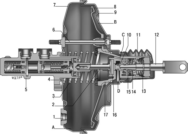
Pic. 9.2. Vacuum booster: 1 - flange fastening the tip; 2 - stock; 3 - diaphragm return spring; 4 – a sealing ring of a flange of the main cylinder; 5 - main cylinder; 6 – hairpin of the amplifier; 7 - amplifier case; 8 - diaphragm; 9 - amplifier housing cover; 10 - piston; 11 - protective cover of the valve body; 12 - pusher; 13 – pusher return spring; 14 - valve spring; 15 - valve; 16 - stock buffer; 17 - valve body; A - vacuum chamber; B - atmospheric chamber; C, D - channels
pressure regulator 1 (pic. 9.3) attached to the bracket 9 with two bolts 2 and 16. At the same time, the front bolt 2 also fastens the fork bracket 3 of the lever 5 of the pressure regulator drive. On the pin of this bracket, a two-arm lever 5 is pivotally fixed with a pin 4. Its upper arm is connected to an elastic lever 10, the other end of which is pivotally connected through an earring 11 to the rear suspension arm bracket.
The bracket 3 together with the lever 5 can be moved relative to the pressure regulator due to the oval holes for the fastening bolt and thereby regulate the force with which the lever 5 acts on the regulator piston.
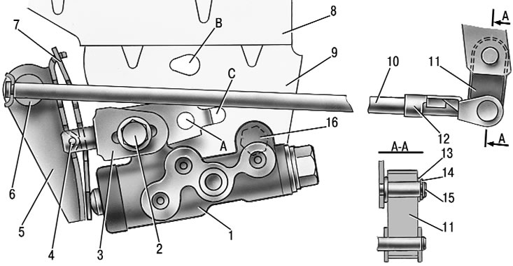
Pic. 9.3. Pressure regulator drive: 1 - pressure regulator; 2, 16 - pressure regulator mounting bolts; 3 - arm of the pressure regulator drive lever; 4 - pin; 5 - pressure regulator drive lever; 6 - axis of the pressure regulator drive lever; 7 – lever spring; 8 - body bracket; 9 - pressure regulator mounting bracket; 10 - elastic lever of the pressure regulator drive; 11 - earring; 12 – earring bracket; 13 - washer; 14 - retaining ring; 15 - bracket pin; A, B, C - holes
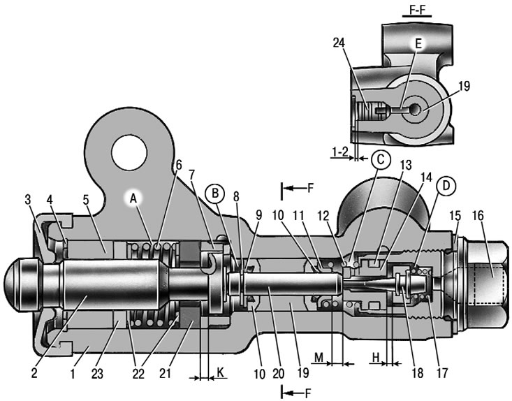
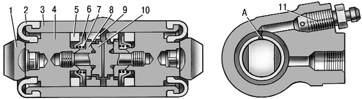
Pic. 9.4. Pressure regulator: 1 - pressure regulator housing; 2 - piston; 3 - protective cap; 4, 8 - retaining rings; 5 - piston sleeve; 6 - piston spring; 7 - housing sleeve; 9, 22 - support washers; 10 - pusher sealing rings; 11 - support plate; 12 - pusher bushing spring; 13 - sealing ring of the valve seat; 14 - valve seat; 15 - sealing gasket; 16 - cork; 17 - valve spring; 18 - valve; 19 - pusher bushing; 20 - pusher; 21 - piston head seal; 23 - piston rod seal; 24 - plug; A, D - chambers connected to the main cylinder; B, C - chambers connected to the wheel cylinders of the rear brakes; E - channel for supplying brake fluid; K, M, H - gaps
The regulator has four chambers: A and D (pic. 9.4) connected to the master cylinder, B - to the left wheel cylinder of the rear brakes, C - to the right.
In the initial position of the brake pedal, piston 2 is pressed by lever 5 (see fig. 9.3) through the leaf spring 7 to the pusher 20 (see fig. 9.4), which, under the action of this force, is pressed against the seat 14 of the valve 18. The valve 18 is pressed from the seat, resulting in gaps K (between piston head and seal 21) and H. Through these gaps, chambers A and D communicate with chambers B and C.
When you press the brake pedal, the fluid through the gaps K and H and chambers B and C enters the wheel cylinders of the brake mechanisms. With an increase in fluid pressure, the force on the piston increases, tending to push it out of the housing. When the force from the fluid pressure exceeds the force from the elastic lever, the piston will begin to move out of the housing, and after it, under the action of springs 12 and 17, the pusher 20 will move along with the sleeve 19 and rings 10. In this case, the gap M increases, and the gaps H and K decrease. When the clearance H is fully selected and the valve 18 isolates chamber D from chamber C, the pusher 20, together with the parts located on it, stops moving after the piston. Now the pressure in chamber C will change depending on the pressure in chamber B. With a further increase in the effort on the brake pedal, the pressure in chambers D, B and A increases, piston 2 continues to move out of the housing, and sleeve 19, together with o-rings 10 and plate 11 under increasing pressure in chamber B, it shifts towards plug 16. In this case, the gap M will begin to decrease. By reducing the volume of chamber C, the pressure in it, and hence in the brake drive, increases and will practically be equal to the pressure in chamber B. When gap K becomes zero, the pressure in chamber B, and hence in chamber C, will increase to a lesser extent. degree than the pressure in chamber A due to the throttling of fluid between the piston head and seal 21. The relationship between the pressure values in chambers B and A is determined by the ratio of the difference in the areas of the head and piston rod to the area of the head.
With an increase in the load of the car, the elastic lever 10 (see fig. 9.3) is loaded more and the force from the lever 5 on the piston increases, i.e. moment of contact between the piston head and the seal 21 (see fig. 9.4) achieved with a higher pressure in the master brake cylinder. Thus, the effectiveness of the rear brakes increases with increasing load.
If the brake circuit fails, the left front - right rear sealing rings 10 and the sleeve 19, under the influence of fluid pressure in chamber B, will move towards the plug 16 until the plate 11 stops in the seat 14. The pressure in the rear brake will be regulated by the part of the regulator, which includes piston 2 with seal 21 and bushing 7. The operation of this part of the regulator, in the event of a failure of the named circuit, is similar to operation in a working system. The nature of the change in pressure at the outlet of the regulator is the same as with a working system.
In the event of a brake circuit failure, the right front - left rear pusher 20 with bushing 19, sealing rings 10, under the influence of brake fluid pressure, moves towards the piston, pushing it out of the housing. The gap M increases and the gap H decreases. When the valve 18 touches the seat 14, the pressure increase in the chamber C stops, that is, the regulator in this case works as a pressure limiter. However, the achieved pressure value is sufficient for reliable operation of the rear brake.
In the housing 1 of the pressure regulator, a hole is made, closed by a plug 24. The leakage of liquid from under the plug when it is squeezed out indicates the leakage of the rings 10.
Pic. 9.5. Master cylinder: 1 - cylinder body; 2, 3 - pistons of the drive circuits of the brakes; 4 - spacer washer; 5 - pusher
The main cylinder is two-section, with a sequential arrangement of pistons (pic. 9.5). Tank 6 is fixed on the body of the main cylinder (see fig. 9.1), in the filler neck of which an emergency brake fluid level sensor is installed. High pressure O-rings and rear wheel cylinder rings are interchangeable.
Front wheel brakes
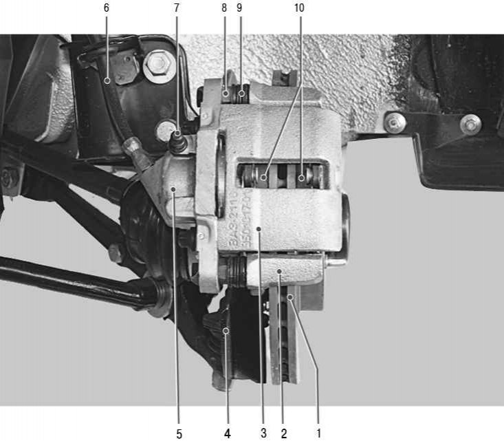
Pic. 9.6. Front wheel brake: 1 - brake disc; 2 - guide pads; 3 - support; 4 - protective cover; 5 - working cylinder; 6 - brake hose; 7 - air release valve; 8 - guide pin; 9 - protective cover of the guide pin; 10 - brake pads
disk, with automatic adjustment of the gap between the pads and the disk, with a floating bracket. The bracket is formed by a caliper 3 (pic. 9.6) and wheel cylinder 5, which are tightened with bolts. The movable bracket is bolted to the fingers 8, which are installed in the holes of the guide 2 of the blocks. Lubrication is put into these holes, rubber covers 9 are installed between the fingers and the guide pads. Brake pads 10 are pressed against the grooves of the guide by springs.
A piston with a sealing ring is installed in the cavity of cylinder 5. Due to the elasticity of this ring, an optimal clearance between the pads and the disc is maintained.
Rear wheel brake (pic. 9.7) drum, with automatic adjustment of the gap between the shoes and the drum. Brake shoes 1 and 6 are actuated by one hydraulic working cylinder 9 with two pistons.
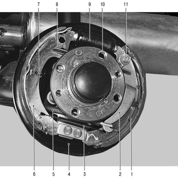
Pic. 9.7. Rear wheel brake: 1 - rear brake shoe; 2 – the lever of a drive of a parking brake; 3 - the lower coupling spring of the shoes; 4 - shield of the brake mechanism; 5 – a cable of a drive of a parking brake; 6 - front brake shoe; 7 - guide spring; 8 - expanding bar; 9 - working cylinder; 10 - the upper coupling spring of the shoes; 11 – a finger of the lever of a drive of a parking brake
Pic. 9.8. Working cylinder: 1 - stop pads; 2 - protective cap; 3 - cylinder body; 4 - piston; 5 - sealant; 6 - support plate; 7 - spring; 8 - crackers; 9 - thrust ring; 10 - stop screw; 11 - fitting; A - a slot on the thrust ring
The automatic clearance adjustment device is located in the working cylinder. Its main element is a split thrust ring 9 (pic. 9.8), mounted on the piston 4 between the shoulder of the stop screw 10 and two crackers 8 with a gap of 1.25–1.65 mm.
Thrust rings 9 are inserted into the cylinder with an interference fit, providing a force for moving the ring along the cylinder mirror of at least 343 N (35 kgf), which exceeds the force on the piston from the coupling springs 3 and 10 (see fig. 9.7) brake pads.
When, due to wear of the linings, the gap of 1.25–1.65 mm is completely selected, the shoulder on the stop screw 10 (see fig. 9.8) is pressed against the shoulder of the ring 9, as a result of which the thrust ring is shifted after the piston by the amount of wear. With the cessation of braking, the pistons are shifted by the force of the coupling springs until the crackers stop against the collar of the thrust ring. Thus, the optimal clearance between the shoes and the drum is automatically maintained.
Parking brake system with a mechanical drive acts on the brake mechanisms of the rear wheels. The parking brake drive consists of a lever 2 (pic. 9.9), adjusting rod 4, equalizer 5, cable 8, lever 2 of the manual drive of the shoes and expander bar 8 (see fig. 9.7).
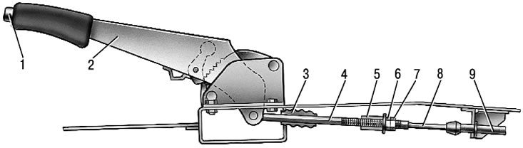
Pic. 9.9. Parking brake drive: 1 - button for fixing the lever; 2 – the lever of a drive of a parking brake; 3 - protective cover; 4 - thrust; 5 - cable equalizer; 6 - adjusting nut; 7 - locknut; 8 - cable; 9 - cable sheath
Emergency brake fluid level sensor mechanical type. Pavilion 2 (pic. 9.10) sensor with a seal 4 and base 3 with a reflector 6 are pressed by a clamping ring 5 to the end face of the tank neck.
A pusher 7 passes through the hole in the base, connected to the float 9 by means of a bushing 8. A movable contact 11 is located on the pusher, and fixed contacts 10 are located on the sensor body. The contact cavity is sealed with a protective cap 1.
When the level of brake fluid in the reservoir drops to the maximum allowable, the moving contact drops onto the fixed contacts and closes the alarm lamp circuit in the instrument cluster.
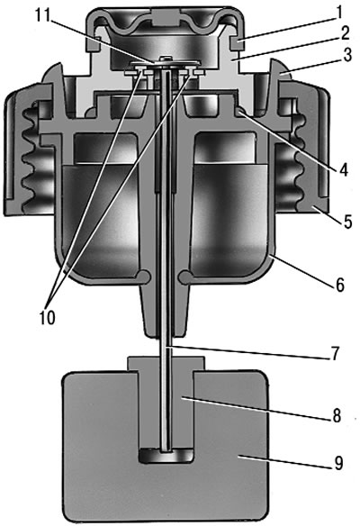
Pic. 9.10. Brake fluid emergency level sensor: 1 - protective cap; 2 – sensor housing; 3 – sensor base; 4 - sealing ring; 5 - clamping ring; 6 - reflector; 7 - pusher; 8 - bushing; 9 - float; 10 - fixed contacts; 11 - moving contact