



Removal
Place the vehicle on the work post, apply the parking brake and turn off the ignition.
Remove the floor tunnel lining in accordance with the requirements of TI 3100.25100.20589.
Disconnect the wiring harness connector from the hand brake lever indicator light switch.
Loosen the adjusting nut 2, Figure 12-1, of the equalizer cable of the hand brake lever and disconnect both cables 1, Figure 12-2, from the equalizer 2 (spanner 10).
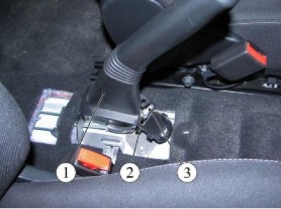
Figure 12-1 - Disconnecting the hand brake lever cables: 1 - hand brake lever; 2 - equalizer cable adjusting nut; 3 - hand brake lever equalizer cable
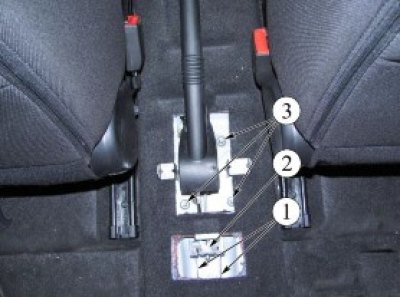
Figure 12-2 - Removing the hand brake lever: 1 - Hand brake actuator torsos; 2 - cable equalizer; 3 - nuts for fastening the hand brake lever
Loosen the three nuts 3 securing the hand brake lever to the floor tunnel studs and remove the lever (replacement head 13, extension and ratchet).
Installation
Install the hand brake lever on the mounting studs and secure with three nuts 3, Figure 12-2. Tightening torque of the nuts 18...24 N·m (1.8...2.4 kgf·m) (replaceable head 13, extension and ratchet, torque wrench).
Install the cables 1 of the hand brake drive into the holes of the equalizer 2.
Tighten the adjusting nut 2, Figure 12-1, of the equalizer cable so that the dimension from the upper end of the adjusting nut to the end of the threaded part of the equalizer cable is 16±0.3 mm (wrench 10, caliper TTTTs-T-125-0.1).
Connect the wiring harness connector to the hand brake lever indicator light switch.
Install the floor tunnel lining in accordance with the requirements of TI 3100.25100.20589.
Adjusting the hand brake drive
Place the vehicle on a two-post lift, apply the parking brake and turn off the ignition (electro-hydraulic lift type P-3.2G with a lifting capacity of 3.2 t).
Lower the hand brake lever.
Tighten and lower the hand brake lever to its original position five times to bring the drive cables into working condition.
Raise the vehicle until the wheels are off the ground and make sure the rear wheels are turning. If this is not the case, check the following items and repair or replace them if necessary:
- hand brake cables;
- rear brake wheel cylinders;
- automatic gap adjustment mechanisms.
Loosen the adjusting nut 2, Figure 12-1, to tighten the cables (spanner 10).
Article based on information from the website (ladaman.ru)
Install the hand brake lever onto the second notch of the toothed sector.
Tighten the adjusting nut until the rear wheels stop turning manually (spanner 10).
Tighten and release the hand brake lever 2-3 times and check the rotation of the rear wheels. If the wheels do not turn. gradually loosen the adjusting nut until the wheels begin to rotate freely. Local contact of the friction lining with the working surface of the drum is allowed (spanner 10).
Check the efficiency of the service brake system in accordance with the requirements of TI 3100.25100.13062.
Present the vehicle to the Quality Control Department. The Quality Control Department will check the vehicle for compliance with the requirements of TU 017200-254-00232934, paragraphs 1.19.9, 1.19.22 in the scope of work performed.