



Removal
Place the vehicle on a two-post lift, apply the parking brake and turn off the ignition (electro-hydraulic lift type P-3.2G with a lifting capacity of 3.2 t).
Remove the rear wheels in accordance with the requirements of TI 3100.25100.20594.
Release the hand brake lever.
Remove the brake drum in accordance with the requirements of paragraph. 9 of this TI.
Remove the guide springs while keeping the spacer bar in contact with the brake shield (flat head screwdriver, pliers).
Remove the upper tension spring (brake spring pliers type 76 41 30 22 from "Stahlwille").
Disconnect the automatic clearance adjustment spring from the shoe (flat head screwdriver, pliers).
Move the brake pads apart.
Unscrew the fitting for fastening the brake pipe 4, Figure 11-1, to the wheel cylinder of the rear brake and install plugs on the brake pipe and in the hole of the wheel cylinder (brake pipe key type 41 08 11 13 from "Stahlwille", technological plugs).
Loosen bolt 2 securing wheel cylinder 3 to shield 1 of the rear brake and remove the cylinder (replacement head 10, extension, ratchet wrench).
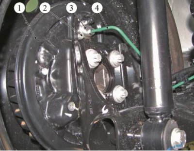
Figure 11-1 - Removing the rear brake wheel cylinder: 1 - rear brake shield; 2 - wheel cylinder mounting bolt; 3 - rear brake wheel cylinder; 4 - brake pipe
Installation
Clean the rear brake components (metal brush).
Install the wheel cylinder onto the rear brake shield and secure it with a bolt. Bolt tightening torque 14 Nm (1.4 kgf·m) (replacement head 10, extension, ratchet wrench, torque wrench).
Remove the plugs from the holes in the wheel cylinder and brake pipe and screw the brake pipe nipple into the hole in the wheel cylinder. The tightening torque of the nipple is 14 N·m (1.4 kgf·m) (wrench for brake pipes type 41 08 11 13 of the company "Stahlwille", replaceable insert 11 type 58 23 10 11 company "Stahlwille", torque wrench type 50 18 00 04 company "Stahlwille").
Hook the spring of the automatic clearance adjustment mechanism to the shoe (flat head screwdriver, pliers).
Install the upper tension spring (brake spring pliers type 76 41 30 22 from "Stahlwille").
Install the guide springs while keeping the spacer bar in contact with the brake shield (flat head screwdriver, pliers).
Check the outer diameter of the brake pads and, if necessary, adjust them in accordance with the requirements of paragraph. 10 real TI.
Install the brake drum in accordance with the requirements of paragraph. 9 of this TI.
Install the rear wheel in accordance with the requirements of TI 3100.25100.20594.
Bleed the brake system and, if necessary, the clutch hydraulic drive in accordance with the requirements of TI 3100.25100.08020.
Check the efficiency of the service brake system in accordance with the requirements of TI 3100.25100.13062.
Present the vehicle to the Quality Control Department. The Quality Control Department will check the vehicle for compliance with the requirements of TU 017200-254-00232934, paragraphs 1.19.9, 1.19.22 in the scope of work performed.