



Removal
Place the vehicle on a two-post lift, apply the parking brake and turn off the ignition (electro-hydraulic lift type P-3.2G with a lifting capacity of 3.2 t).
Remove the floor tunnel lining in accordance with the requirements of TI 3100.25100.20589.
Lower the hand brake lever down to the stop.
Loosen the adjusting nut 2, Figure 12-1, of the hand brake lever and disconnect both cables 2, Figure 13-1, from the equalizer 3 (spanner 10).
Remove the ends 1, Figure 13-1, of the cable sheaths 2 from the holes in the floor tunnel (flat head screwdriver, pliers).
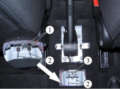
Figure 13-1 - Disconnecting the drive cables from the hand brake lever: 1 - cable lining tip; 2 - hand brake cable; 3 - cable equalizer
Remove the rear wheels in accordance with the requirements of TI 3100.25100.20594.
Unscrew the three nuts 1, Figure 13-2, fastenings and remove the protective screen 2 of the body floor (replacement head 24, extension, ratchet handle).
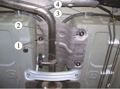
Figure 13-2 - Disconnecting the cables from the body: 1 - nuts for fastening the protective screen of the body floor; 2 - protective screen of the body floor; 3 - cable sheaths; 4 - cable sheath fastening brackets
Release the casings of the 3 cables from the brackets of the 4 fastening to the bottom of the car body (flat head screwdriver).
Remove the rear brake pads in accordance with the requirements of Section 10 of this technical instruction.
Disconnect the cables from the brake shoe drive levers and remove the ends 1, Figure 13-3, of the cables 2 from the holes in the brake shields (flat head screwdriver, pliers).
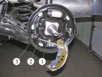
Figure 13-3 - Disconnecting the cables from the brake shield: 1 - cable; 2 - cable tip; 3 - brake shield
Remove the cables from the guide holes in the brackets on the rear suspension arms and in the brackets that mount the rear suspension arms to the body.
Remove the cables.
Installation
Install the cables into the guide holes in the brackets that mount the rear suspension arms to the body and in the brackets on the rear suspension arms.
Install the cable sheath tips into the brake shield holes (flat head screwdriver, pliers).
Install the cable sheath tips into the holes in the body floor tunnel and secure the cable sheaths in the mounting brackets to the body bottom (flat head screwdriver, pliers).
Install the rear brake pads in accordance with the requirements of Section 10 of this technological instruction.
Install the rear wheels in accordance with the requirements of TI 3100.25100.20594.
Connect the cables to the hand brake lever equalizer.
Adjust the hand brake lever in accordance with the requirements of Section 12 of this technological instruction.
Install the floor tunnel lining in accordance with the requirements of TI 3100.25100.20589.
Check the efficiency of the service brake system in accordance with the requirements of TI 3100.25100.13062.
Present the vehicle to the Quality Control Department. The Quality Control Department will check the vehicle for compliance with the requirements of TU 017200-254-00232934, paragraphs 1.19.9, 1.19.22 in the scope of work performed.