



Removal
Place the vehicle on a two-post lift, apply the parking brake and turn off the ignition (electro-hydraulic lift type P-3.2G with a lifting capacity of 3.2 t).
Raise the vehicle to a height convenient for performing work.
Loosen screw 1, Figure 16-2, of the speed sensor mount and remove speed sensor 2 from the hole on steering knuckle 3 (torx T30 replacement bit, extension, ratchet wrench).

Figure 16-2 - Removing the front wheel speed sensor: 1 - screw for fastening the speed sensor; 2 - front wheel speed sensor; 3 - steering knuckle
Remove harness 1, Figure 16-3, of the speed sensor wires from the slots of bracket 3 on the front suspension strut and brackets 4 on the engine compartment mudguard.
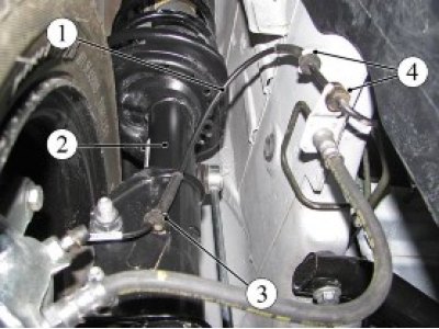
Figure 16-3 - Disconnecting the Front Wheel Speed Sensor Wiring Harness: 1 - Front wheel speed sensor wiring harness; 2 - front suspension strut; 3 - bracket for fastening the speed sensor wiring harness to the front suspension strut 4 - bracket for fastening the speed sensor wiring harness to the engine compartment mudguard
Original is available on this resource ladaman
Disconnect the speed sensor wiring harness connector from the front wiring harness and the retainer on the vehicle body and remove the speed sensor.
Installation
Connect the speed sensor wiring harness connector to the front wiring harness and the retainer on the vehicle body.
Install sensor 2, Figure 16-2, speed in the mounting hole on steering knuckle 3 and secure with screw 1. Tightening torque of the screw 6...7 N·m (0.6...0.7 kgf·m) (torx T30 replacement bit, extension, ratchet wrench, torque wrench).
Install harness 1, Figure 16-3, of the speed sensor wires into the groove of bracket 3 of the front suspension strut and into the grooves of brackets 4 on the mudguard of the engine compartment.
Present the vehicle to the Quality Control Department. The Quality Control Department will check the vehicle for compliance with the requirements of TU 017200-254-00232934, paragraphs 1.19.21, 1.19.22 in the scope of work performed.